Amateur Extra / Topics
E5 Electrical Principles
E5 Electrical Principles (Amateur Extra questions)49 questions in 4 groups. The exam asks 4 questions from this topic, one from each group.
E5A Resonance and Q: characteristics of resonant circuits; series and parallel resonance; definitions and effects of Q; half-power bandwidth
E5A01
What can cause the voltage across reactances in a series RLC circuit to be higher than the voltage applied to the entire circuit?
- A. Resonance
- B. Capacitance
- C. Low quality factor (Q)
- D. Resistance
Show answer
A. Resonance
At resonance in a series RLC circuit, the inductive and capacitive reactances cancel, so only the resistance limits the current and the current is large. That current flowing through each reactance develops I x XL across the inductor and I x XC across the capacitor, which can be Q times the applied voltage; the two voltages are opposite in phase, so they cancel in the total and the source never sees them.
- B. Capacitance alone does not raise the voltage; a capacitor's voltage exceeds the source voltage only near resonance, where the inductor cancels its reactance and the current becomes large.
- C. A low Q means resistance dominates the circuit, which limits the current and keeps the reactive voltages small; voltage magnification grows with high Q, not low Q.
- D. Resistance limits the current at resonance, so more resistance lowers the voltage across the reactances rather than raising it.
E5A02
What is the resonant frequency of an RLC circuit if R is 22 ohms, L is 50 microhenries, and C is 40 picofarads?
- A. 44.72 MHz
- B. 22.36 MHz
- C. 3.56 MHz
- D. 1.78 MHz
Show answer
C. 3.56 MHz
Resonant frequency depends only on L and C: f = 1 / (2 x π x √(L x C)). With L in microhenries and C in picofarads, the result in megahertz is 1000 / (2 x π x √(50 x 40)) = 1000 / (2 x π x 44.72) = 1000 / 281.0 = 3.56 MHz. The 22-ohm resistance affects Q, not the resonant frequency.
- A. 44.72 is √(50 x 40), an intermediate step in the calculation, not the resonant frequency.
- B. 22.36 million is 1 / √(L x C) without the 2 x π; that is the angular frequency in radians per second, not the frequency in hertz.
- D. 1.78 MHz is half the correct value, the result of dividing by 4 x π instead of 2 x π.
E5A03
What is the magnitude of the impedance of a series RLC circuit at resonance?
- A. High, compared to the circuit resistance
- B. Approximately equal to capacitive reactance
- C. Approximately equal to inductive reactance
- D. Approximately equal to circuit resistance
Show answer
D. Approximately equal to circuit resistance
At resonance, the inductive reactance and capacitive reactance of a series circuit are equal and opposite, so they cancel. The only opposition left is the circuit resistance, so the impedance is at its minimum and approximately equals R.
- A. High impedance at resonance is a property of parallel resonant circuits; in a series circuit the reactances cancel and leave only the resistance, the minimum impedance.
- B. The capacitive reactance is cancelled by an equal inductive reactance at resonance, so it does not set the impedance.
- C. The inductive reactance is cancelled by an equal capacitive reactance at resonance, so it does not set the impedance.
E5A04
What is the magnitude of the impedance of a parallel RLC circuit at resonance?
- A. Approximately equal to circuit resistance
- B. Approximately equal to inductive reactance
- C. Low compared to the circuit resistance
- D. High compared to the circuit resistance
Show answer
A. Approximately equal to circuit resistance
In a parallel RLC circuit at resonance, the inductor and capacitor branch currents are equal and opposite, so they cancel at the input and the LC pair acts like an open circuit. The source sees only the resistance in parallel with it, so the impedance rises to its maximum, which is approximately R.
- B. The two reactances cancel each other at resonance, so neither one sets the impedance; the resistance does.
- C. The impedance of a parallel circuit falls below R away from resonance, where one reactive branch draws current; at resonance the reactive branches draw no net current, so the impedance is R, not less.
- D. At resonance the reactive branches drop out and only the parallel resistance remains, so the impedance rises to R but no higher.
E5A05
What is the result of increasing the Q of an impedance-matching circuit?
- A. Matching bandwidth is decreased
- B. Matching bandwidth is increased
- C. Losses increase
- D. Harmonics increase
Show answer
A. Matching bandwidth is decreased
Bandwidth and Q are inversely related: bandwidth = f / Q. Raising the Q of a matching network makes it more frequency selective, so it holds a good match over a narrower range of frequencies and needs retuning more often as the operating frequency changes.
- B. Higher Q narrows the bandwidth; a wider matching bandwidth comes from lower Q.
- C. Higher Q raises circulating currents and voltages, which can add loss in imperfect components, but that depends on component quality; the result that always follows from higher Q is a narrower bandwidth.
- D. A higher Q network is more selective, so it attenuates harmonics more, not less.
E5A06
What is the magnitude of the circulating current within the components of a parallel LC circuit at resonance?
- A. It is at a minimum
- B. It is at a maximum
- C. It equals 1 divided by the quantity 2 times pi, times the square root of (inductance L multiplied by capacitance C)
- D. It equals 2 times pi, times the square root of (inductance L multiplied by capacitance C)
Show answer
B. It is at a maximum
At resonance, energy swings back and forth between the inductor's magnetic field and the capacitor's electric field. The current circulating around the LC loop is about Q times the current drawn from the source and is at its maximum at resonance, even though the line current is at its minimum.
- A. The current drawn from the source (the line current) is at a minimum at resonance; the current circulating inside the tank is at a maximum.
- C. 1 / (2 x π x √(L x C)) is the formula for the resonant frequency, not for a current.
- D. 2 x π x √(L x C) is the period of one cycle at resonance, in seconds (the reciprocal of the resonant frequency), not a current.
E5A07
What is the magnitude of the current at the input of a parallel RLC circuit at resonance?
- A. Minimum
- B. Maximum
- C. R/L
- D. L/R
Show answer
A. Minimum
At resonance, the inductor and capacitor branch currents in a parallel circuit are equal and opposite, so they cancel at the input. The source supplies only the current for the resistance; the impedance is at its maximum, so the input current is at its minimum.
- B. Maximum current describes the current circulating inside the tank, or the input current of a series circuit at resonance, not the input current of a parallel circuit.
- C. R / L is the reciprocal of an RL time constant, with units of 1 per second; it is not a current.
- D. L / R is the time constant of an RL circuit, in seconds; it is not a current.
E5A08
What is the phase relationship between the current through and the voltage across a series resonant circuit at resonance?
- A. The voltage leads the current by 90 degrees
- B. The current leads the voltage by 90 degrees
- C. The voltage and current are in phase
- D. The voltage and current are 180 degrees out of phase
Show answer
C. The voltage and current are in phase
At resonance, a series circuit's inductive and capacitive reactances cancel, leaving a purely resistive impedance. In a resistance, the voltage and current rise and fall together, so they are in phase (a phase angle of zero).
- A. Voltage leading current by 90 degrees describes a pure inductance, not a resonant circuit where the reactances cancel.
- B. Current leading voltage by 90 degrees describes a pure capacitance, not a resonant circuit where the reactances cancel.
- D. At series resonance, the voltages across the inductor and the capacitor are 180 degrees apart from each other, but the source voltage and current are in phase.
E5A09
How is the Q of an RLC parallel resonant circuit calculated?
- A. Reactance of either the inductance or capacitance divided by the resistance
- B. Reactance of either the inductance or capacitance multiplied by the resistance
- C. Resistance divided by the reactance of either the inductance or capacitance
- D. Reactance of the inductance multiplied by the reactance of the capacitance
Show answer
C. Resistance divided by the reactance of either the inductance or capacitance
In a parallel resonant circuit, the resistance is in parallel with the reactances, so a larger R loads the circuit less and gives a higher Q: Q = R / X, where X is the reactance of either the inductor or the capacitor (they are equal at resonance). This is the inverse of the series formula.
- A. Reactance divided by resistance (X / R) is the Q of a series resonant circuit, where resistance is in series with the reactances.
- B. Multiplying reactance by resistance gives a quantity in ohms squared, not the unitless ratio that Q is.
- D. XL x XC equals L / C, which is used to find the characteristic impedance of an LC circuit (the square root of L / C); it is not Q.
E5A10
What is the resonant frequency of an RLC circuit if R is 33 ohms, L is 50 microhenries, and C is 10 picofarads?
- A. 7.12 MHz
- B. 23.5 kHz
- C. 7.12 kHz
- D. 23.5 MHz
Show answer
A. 7.12 MHz
Resonant frequency depends only on L and C: f = 1 / (2 x π x √(L x C)). With L in microhenries and C in picofarads, the result in megahertz is 1000 / (2 x π x √(50 x 10)) = 1000 / (2 x π x 22.36) = 1000 / 140.5 = 7.12 MHz. The 33-ohm resistance affects Q, not the resonant frequency.
- B. 23.5 kHz is far too low; 50 µH and 10 pF resonate at 7.12 MHz.
- C. 7.12 kHz has the right digits but the wrong prefix; the result is 7.12 MHz, 1000 times higher.
- D. 23.5 MHz is about 3.3 times too high; f = 1 / (2 x π x √(L x C)) with 50 µH and 10 pF gives 7.12 MHz.
E5A11
What is the half-power bandwidth of a resonant circuit that has a resonant frequency of 7.1 MHz and a Q of 150?
- A. 157.8 Hz
- B. 315.6 Hz
- C. 47.3 kHz
- D. 23.67 kHz
Show answer
C. 47.3 kHz
Half-power bandwidth equals the resonant frequency divided by Q: BW = f / Q = 7,100,000 Hz / 150 = 47,333 Hz, or 47.3 kHz. This is the full width between the two half-power (-3 dB) points.
- A. 157.8 Hz is half of 315.6 Hz, which comes from dividing by Q twice; the bandwidth divides the frequency by Q only once.
- B. 315.6 Hz is 7.1 MHz divided by Q twice (by 150²); the bandwidth divides the frequency by Q only once.
- D. 23.67 kHz is half the bandwidth, the distance from the center frequency to one half-power point, not the full width between the two points.
E5A12
What is the half-power bandwidth of a resonant circuit that has a resonant frequency of 3.7 MHz and a Q of 118?
- A. 436.6 kHz
- B. 218.3 kHz
- C. 31.4 kHz
- D. 15.7 kHz
Show answer
C. 31.4 kHz
Half-power bandwidth equals the resonant frequency divided by Q: BW = f / Q = 3,700,000 Hz / 118 = 31,356 Hz, or 31.4 kHz. This is the full width between the two half-power (-3 dB) points.
- A. 436.6 comes from multiplying 3.7 by 118; the bandwidth divides the frequency by Q instead.
- B. 218.3 kHz is half of 3.7 x 118; the bandwidth divides the frequency by Q rather than multiplying.
- D. 15.7 kHz is half the bandwidth, the distance from the center frequency to one half-power point, not the full width between the two points.
E5A13
What is an effect of increasing Q in a series resonant circuit?
- A. Fewer components are needed for the same performance
- B. Parasitic effects are minimized
- C. Internal voltages increase
- D. Phase shift can become uncontrolled
Show answer
C. Internal voltages increase
At resonance, the voltage across the inductor and across the capacitor of a series circuit is Q times the applied voltage. Raising Q raises these internal voltages, so components in a high-Q circuit must be rated for voltages well above the source voltage.
- A. Q describes selectivity and loss, not part count; raising Q does not reduce the number of components needed.
- B. Parasitic effects, such as lead inductance and stray capacitance, come from component construction and layout; raising Q does not reduce them.
- D. Phase shift through a resonant circuit follows frequency in a predictable way; higher Q makes the phase change more steeply near resonance, but it does not become uncontrolled.
E5B Time constants and phase relationships: RL and RC time constants; phase angle in reactive circuits and components; admittance and susceptance
E5B01
What is the term for the time required for the capacitor in an RC circuit to be charged to 63.2% of the applied voltage or to discharge to 36.8% of its initial voltage?
- A. An exponential rate of one
- B. One time constant
- C. One exponential period
- D. A time factor of one
Show answer
B. One time constant
One time constant (τ = R x C for an RC circuit) is the time a capacitor takes to charge to 63.2% of the applied voltage, or to discharge to 36.8% of its starting voltage. These figures come from the exponential curve: 1 - 1/e = 0.632 and 1/e = 0.368, where e is about 2.718.
- A. "Exponential rate of one" is not a standard term; the interval described is one time constant.
- C. "Exponential period" is not a standard term; the interval described is one time constant.
- D. "Time factor" is not a standard term; the interval described is one time constant.
E5B02
What letter is commonly used to represent susceptance?
- A. G
- B. X
- C. Y
- D. B
Show answer
D. B
Susceptance is represented by B. It is the reciprocal of reactance and the imaginary part of admittance, which is written Y = G + jB and measured in siemens.
- A. G represents conductance, the real part of admittance and the reciprocal of resistance.
- B. X represents reactance, the opposition of inductors and capacitors to AC, measured in ohms.
- C. Y represents admittance, the reciprocal of impedance, which combines conductance and susceptance.
E5B03
How is impedance in polar form converted to an equivalent admittance?
- A. Take the reciprocal of the angle and change the sign of the magnitude
- B. Take the reciprocal of the magnitude and change the sign of the angle
- C. Take the square root of the magnitude and add 180 degrees to the angle
- D. Square the magnitude and subtract 90 degrees from the angle
Show answer
B. Take the reciprocal of the magnitude and change the sign of the angle
Admittance is the reciprocal of impedance (Y = 1 / Z). In polar form, the reciprocal of a complex number has the reciprocal magnitude and the opposite angle, so an impedance of 50 ohms at 30 degrees becomes an admittance of 0.02 siemens at -30 degrees.
- A. Taking the reciprocal of an angle has no meaning here; the reciprocal applies to the magnitude, and the angle changes sign.
- C. Neither a square root nor a 180-degree shift is part of the conversion; Y = 1 / Z inverts the magnitude and reverses the sign of the angle.
- D. Squaring the magnitude and subtracting 90 degrees does not invert a complex number; Y = 1 / Z inverts the magnitude and reverses the sign of the angle.
E5B04
What is the time constant of a circuit having two 220-microfarad capacitors and two 1-megohm resistors, all in parallel?
- A. 55 seconds
- B. 110 seconds
- C. 440 seconds
- D. 220 seconds
Show answer
D. 220 seconds
The time constant is τ = R x C. Two 220 µF capacitors in parallel add to 440 µF, and two 1 MΩ resistors in parallel give 0.5 MΩ, so τ = 500,000 ohms x 0.000440 farads = 220 seconds.
- A. 55 seconds treats the capacitors as if they were in series (110 µF) while using the parallel resistance (0.5 MΩ); capacitors in parallel add.
- B. 110 seconds halves the resistance without doubling the capacitance; in parallel, the capacitance doubles to 440 µF while the resistance halves to 0.5 MΩ.
- C. 440 seconds doubles the capacitance but leaves the resistance at 1 MΩ; two 1 MΩ resistors in parallel give 0.5 MΩ.
E5B05
What is the effect on the magnitude of pure reactance when it is converted to susceptance?
- A. It is unchanged
- B. The sign is reversed
- C. It is shifted by 90 degrees
- D. It is replaced by its reciprocal
Show answer
D. It is replaced by its reciprocal
Susceptance is the reciprocal of reactance, B = 1 / X, so converting a pure reactance to susceptance replaces its magnitude with its reciprocal. For example, 100 ohms of reactance becomes 0.01 siemens of susceptance.
- A. The magnitude does change: 100 ohms of reactance becomes 0.01 siemens of susceptance.
- B. The sign of the imaginary part does flip when 1 / (jX) is worked out, but a sign is not part of a magnitude; the magnitude becomes its reciprocal.
- C. A 90-degree shift describes the phase between voltage and current in a reactance; it is not what happens to the magnitude when reactance becomes susceptance.
E5B06
What is susceptance?
- A. The magnetic impedance of a circuit
- B. The ratio of magnetic field to electric field
- C. The imaginary part of admittance
- D. A measure of the efficiency of a transformer
Show answer
C. The imaginary part of admittance
Admittance (Y), the reciprocal of impedance, is written in rectangular form as Y = G + jB. The real part G is conductance and the imaginary part B is susceptance, both measured in siemens.
- A. "Magnetic impedance" is not what susceptance means; the opposition to magnetic flux in a magnetic circuit is called reluctance.
- B. Ratios of electric and magnetic field strength describe a radio wave in space (the wave impedance, about 377 ohms in free space); susceptance is a circuit quantity.
- D. Transformer efficiency is output power divided by input power; it is unrelated to susceptance.
E5B07
What is the phase angle between the voltage across and the current through a series RLC circuit if XC is 500 ohms, R is 1 kilohm, and XL is 250 ohms?
- A. 68.2 degrees with the voltage leading the current
- B. 14.0 degrees with the voltage leading the current
- C. 14.0 degrees with the voltage lagging the current
- D. 68.2 degrees with the voltage lagging the current
Show answer
C. 14.0 degrees with the voltage lagging the current
The net reactance is X = XL - XC = 250 - 500 = -250 ohms, and the phase angle is arctan(X / R) = arctan(-250 / 1000) = -14.0 degrees. A negative angle means the circuit is net capacitive, so the voltage lags the current by 14.0 degrees.
- A. Both parts are wrong: a 68.2-degree angle would need a net reactance 2.5 times the resistance, and a leading voltage would need XL larger than XC.
- B. The angle is right but the direction is wrong; XC is larger than XL, so the circuit is capacitive and the voltage lags the current.
- D. The direction is right but the angle is wrong; a 68.2-degree angle would need a net reactance 2.5 times the resistance, and here it is only 250 ohms against 1000 ohms.
E5B08
What is the phase angle between the voltage across and the current through a series RLC circuit if XC is 300 ohms, R is 100 ohms, and XL is 100 ohms?
- A. 63 degrees with the voltage lagging the current
- B. 63 degrees with the voltage leading the current
- C. 27 degrees with the voltage leading the current
- D. 27 degrees with the voltage lagging the current
Show answer
A. 63 degrees with the voltage lagging the current
The net reactance is X = XL - XC = 100 - 300 = -200 ohms, and the phase angle is arctan(X / R) = arctan(-200 / 100) = -63.4 degrees. A negative angle means the circuit is net capacitive, so the voltage lags the current by about 63 degrees.
- B. The angle is right but the direction is wrong; XC is larger than XL, so the circuit is capacitive and the voltage lags the current.
- C. Both parts are wrong: 27 degrees comes from inverting the ratio (arctan of 100 / 200), and the circuit is capacitive, so the voltage lags.
- D. The direction is right but the angle is wrong; 27 degrees comes from inverting the ratio (arctan of R / X instead of X / R).
E5B09
What is the relationship between the AC current through a capacitor and the voltage across a capacitor?
- A. Voltage and current are in phase
- B. Voltage and current are 180 degrees out of phase
- C. Voltage leads current by 90 degrees
- D. Current leads voltage by 90 degrees
Show answer
D. Current leads voltage by 90 degrees
A capacitor's voltage builds up only as charge flows into it, so the current peaks first, a quarter cycle (90 degrees) before the voltage. The memory aid "ELI the ICE man" puts I (current) before E (voltage) in ICE, where C stands for capacitor.
- A. Voltage and current in phase describes a pure resistance, not a capacitor.
- B. A 180-degree relationship does not occur between voltage and current in an ideal capacitor; the shift is 90 degrees, with current leading.
- C. Voltage leading current by 90 degrees describes an inductor, the opposite of a capacitor.
E5B10
What is the relationship between the AC current through an inductor and the voltage across an inductor?
- A. Voltage leads current by 90 degrees
- B. Current leads voltage by 90 degrees
- C. Voltage and current are 180 degrees out of phase
- D. Voltage and current are in phase
Show answer
A. Voltage leads current by 90 degrees
An inductor opposes changes in current, so the current builds up only after voltage is applied, and the voltage peaks a quarter cycle (90 degrees) before the current. The memory aid "ELI the ICE man" puts E (voltage) before I (current) in ELI, where L stands for inductor.
- B. Current leading voltage by 90 degrees describes a capacitor, the opposite of an inductor.
- C. A 180-degree relationship does not occur between voltage and current in an ideal inductor; the shift is 90 degrees, with voltage leading.
- D. Voltage and current in phase describes a pure resistance, not an inductor.
E5B11
What is the phase angle between the voltage across and the current through a series RLC circuit if XC is 25 ohms, R is 100 ohms, and XL is 75 ohms?
- A. 27 degrees with the voltage lagging the current
- B. 27 degrees with the voltage leading the current
- C. 63 degrees with the voltage lagging the current
- D. 63 degrees with the voltage leading the current
Show answer
B. 27 degrees with the voltage leading the current
The net reactance is X = XL - XC = 75 - 25 = +50 ohms, and the phase angle is arctan(X / R) = arctan(50 / 100) = +26.6 degrees. A positive angle means the circuit is net inductive, so the voltage leads the current by about 27 degrees.
- A. The angle is right but the direction is wrong; XL is larger than XC, so the circuit is inductive and the voltage leads the current.
- C. Both parts are wrong: 63 degrees comes from inverting the ratio (arctan of 100 / 50), and the circuit is inductive, so the voltage leads.
- D. The direction is right but the angle is wrong; 63 degrees comes from inverting the ratio (arctan of R / X instead of X / R).
E5B12
What is admittance?
- A. The inverse of impedance
- B. The term for the gain of a field effect transistor
- C. The inverse of reactance
- D. The term for the on-impedance of a field effect transistor
Show answer
A. The inverse of impedance
Admittance (Y) is the inverse of impedance: Y = 1 / Z, measured in siemens. Impedance describes how strongly a circuit opposes AC; admittance describes how readily it passes AC.
- B. The gain of a field effect transistor is described by its transconductance, the change in drain current per change in gate voltage; it is not admittance.
- C. The inverse of reactance is susceptance, which is only the imaginary part of admittance.
- D. A conducting FET's resistance is its on-resistance, RDS(on), the resistance from drain to source; it is not admittance.
E5C Coordinate systems and phasors in electronics: rectangular coordinates; polar coordinates; phasors; logarithmic axes
E5C01
Which of the following represents pure capacitive reactance of 100 ohms in rectangular notation?
- A. 0 - j100
- B. 0 + j100
- C. 100 - j0
- D. 100 + j0
Show answer
A. 0 - j100
Rectangular notation writes impedance as R ± jX: the real part is resistance and the imaginary part is reactance, positive for inductive and negative for capacitive. A pure capacitive reactance of 100 ohms has no resistance, so it is 0 - j100.
- B. 0 + j100 has a positive imaginary part, which is a pure inductive reactance of 100 ohms.
- C. 100 - j0 has a real part of 100 and no reactance, which is a pure resistance of 100 ohms.
- D. 100 + j0 has a real part of 100 and no reactance, which is a pure resistance of 100 ohms.
E5C02
How are impedances described in polar coordinates?
- A. By X and R values
- B. By real and imaginary parts
- C. By magnitude and phase angle
- D. By Y and G values
Show answer
C. By magnitude and phase angle
Polar coordinates describe an impedance by its magnitude (the total opposition in ohms) and its phase angle (how far current and voltage are shifted from each other), written for example as 50 ohms at 30 degrees.
- A. R and X values (resistance and reactance) describe an impedance in rectangular form, not polar form.
- B. Real and imaginary parts describe an impedance in rectangular form, not polar form.
- D. Y and G are the symbols for admittance and conductance; they describe admittance, not the polar form of an impedance.
E5C03
Which of the following represents a pure inductive reactance in polar coordinates?
- A. A positive 45 degree phase angle
- B. A negative 45 degree phase angle
- C. A positive 90 degree phase angle
- D. A negative 90 degree phase angle
Show answer
C. A positive 90 degree phase angle
A pure inductive reactance has no resistance and a positive imaginary part (+jX), so it points straight up from the origin: in polar form, its magnitude is X at a phase angle of +90 degrees. For example, 0 + j100 ohms is 100 ohms at +90 degrees.
- A. A +45-degree angle describes equal resistance and inductive reactance, such as 100 + j100 ohms, not a pure reactance.
- B. A -45-degree angle describes equal resistance and capacitive reactance, such as 100 - j100 ohms.
- D. A -90-degree angle describes a pure capacitive reactance.
E5C04
What type of Y-axis scale is most often used for graphs of circuit frequency response?
- A. Linear
- B. Scatter
- C. Random
- D. Logarithmic
Show answer
D. Logarithmic
Frequency response graphs usually show gain or attenuation in decibels, a logarithmic scale, so large and small ratios fit on the same graph and equal steps represent equal ratios. The frequency axis is often logarithmic as well.
- A. A linear scale crowds small values near zero, so responses spanning many orders of magnitude, such as a filter's stopband, become hard to read.
- B. A scatter plot is a kind of graph made of individual data points, not a type of axis scale.
- C. There is no "random" axis scale; axis divisions follow a defined rule.
E5C05
What kind of diagram is used to show the phase relationship between impedances at a given frequency?
- A. Venn diagram
- B. Near field diagram
- C. Phasor diagram
- D. Far field diagram
Show answer
C. Phasor diagram
A phasor diagram draws AC quantities, such as impedances, voltages and currents, as arrows whose length is the magnitude and whose angle is the phase at a given frequency. It shows at a glance how resistance and reactance combine.
- A. A Venn diagram shows overlapping sets in logic and mathematics, not phase relationships.
- B. The near field is the region close to an antenna; it is not a diagram of impedance phase relationships.
- D. The far field is the region well away from an antenna where its radiation pattern is measured; it is not a diagram of impedance phase relationships.
E5C06
What does the impedance 50 - j25 ohms represent?
- A. 50 ohms resistance in series with 25 ohms inductive reactance
- B. 50 ohms resistance in series with 25 ohms capacitive reactance
- C. 25 ohms resistance in series with 50 ohms inductive reactance
- D. 25 ohms resistance in series with 50 ohms capacitive reactance
Show answer
B. 50 ohms resistance in series with 25 ohms capacitive reactance
In rectangular form, the real part of an impedance is resistance and the imaginary part is reactance, with a negative sign for capacitive reactance. So 50 - j25 ohms is 50 ohms of resistance in series with 25 ohms of capacitive reactance.
- A. Inductive reactance would carry a positive sign, 50 + j25; the minus sign marks capacitive reactance.
- C. 25 ohms of resistance with 50 ohms of inductive reactance would be written 25 + j50; the resistance is the real part, 50, and the sign is negative.
- D. 25 ohms of resistance with 50 ohms of capacitive reactance would be written 25 - j50; the real part, here 50, is the resistance.
E5C07
Where is the impedance of a pure resistance plotted on rectangular coordinates?
- A. On the vertical axis
- B. On a line through the origin, slanted at 45 degrees
- C. On a horizontal line, offset vertically above the horizontal axis
- D. On the horizontal axis
Show answer
D. On the horizontal axis
On rectangular impedance coordinates, the horizontal axis is resistance and the vertical axis is reactance. A pure resistance has zero reactance, so it lies on the horizontal axis at its resistance value.
- A. The vertical axis is where pure reactances lie, with no resistance.
- B. A 45-degree line through the origin holds impedances with equal resistance and reactance, such as 100 + j100 ohms.
- C. A horizontal line above the axis holds impedances with the same positive (inductive) reactance and differing resistance, not a pure resistance.
E5C08
What coordinate system is often used to display the phase angle of a circuit containing resistance, inductive, and/or capacitive reactance?
- A. Maidenhead grid
- B. Faraday grid
- C. Elliptical coordinates
- D. Polar coordinates
Show answer
D. Polar coordinates
Polar coordinates express an impedance as a magnitude and a phase angle, so they show the phase angle of a circuit with resistance and reactance directly, as the angle of a line from the origin.
- A. The Maidenhead grid is the geographic locator system amateurs use to describe station locations, not a way to show phase angle.
- B. A "Faraday grid" is not a coordinate system; Faraday's name is attached to electromagnetic induction and to the shielding enclosure called a Faraday cage.
- C. Elliptical coordinates are a mathematical system built on ellipses and hyperbolas; they are not used to display circuit phase angles.
E5C09
When using rectangular coordinates to graph the impedance of a circuit, what do the axes represent?
- A. The X axis represents the resistive component, and the Y axis represents the reactive component
- B. The X axis represents the reactive component, and the Y axis represents the resistive component
- C. The X axis represents the phase angle, and the Y axis represents the magnitude
- D. The X axis represents the magnitude, and the Y axis represents the phase angle
Show answer
A. The X axis represents the resistive component, and the Y axis represents the reactive component
On a rectangular impedance graph, the X (horizontal) axis is resistance and the Y (vertical) axis is reactance, with inductive reactance above the axis and capacitive reactance below it. An impedance R + jX is plotted at the point (R, X).
- B. The axes are reversed; resistance goes on the horizontal axis and reactance on the vertical axis.
- C. Phase angle and magnitude are polar quantities; they are not the axes of a rectangular graph.
- D. Magnitude and phase angle are polar quantities; they are not the axes of a rectangular graph.
E5C10
Which point on Figure E5-1 best represents the impedance of a series circuit consisting of a 400-ohm resistor and a 38-picofarad capacitor at 14 MHz?
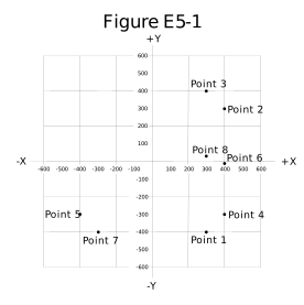
Figure E5-1 - A. Point 2
- B. Point 4
- C. Point 5
- D. Point 6
Show answer
B. Point 4
With f in megahertz and C in picofarads, the capacitor's reactance is XC = 1,000,000 / (2 x π x f x C) = 1,000,000 / (2 x π x 14 x 38) = 299 ohms, about 300 ohms. Capacitive reactance is negative, so the impedance is 400 - j300 ohms, the point at 400 on the horizontal axis and -300 on the vertical axis: Point 4.
- A. Point 2 is at 400 + j300, a resistance with inductive reactance; a capacitor puts the point below the horizontal axis.
- C. Point 5 is at -400 - j300, which has negative resistance; a resistor puts the point to the right of the vertical axis.
- D. Point 6 lies on the horizontal axis at 400 ohms, a pure resistance with no reactance; the capacitor adds about 300 ohms of capacitive reactance.
E5C11
Which point in Figure E5-1 best represents the impedance of a series circuit consisting of a 300-ohm resistor and an 18-microhenry inductor at 3.505 MHz?
Figure E5-1 - A. Point 1
- B. Point 3
- C. Point 7
- D. Point 8
Show answer
B. Point 3
With f in megahertz and L in microhenries, the inductor's reactance is XL = 2 x π x f x L = 2 x π x 3.505 x 18 = 396 ohms, about 400 ohms. Inductive reactance is positive, so the impedance is 300 + j400 ohms, the point at 300 on the horizontal axis and +400 on the vertical axis: Point 3.
- A. Point 1 is at 300 - j400, a resistance with capacitive reactance; an inductor puts the point above the horizontal axis.
- C. Point 7 is at -300 - j400, which has negative resistance and capacitive reactance; neither fits a resistor and an inductor.
- D. Point 8 sits close to the horizontal axis at 300 ohms, showing very little reactance; the inductor adds about 396 ohms of inductive reactance.
E5C12
Which point on Figure E5-1 best represents the impedance of a series circuit consisting of a 300-ohm resistor and a 19-picofarad capacitor at 21.200 MHz?
Figure E5-1 - A. Point 1
- B. Point 3
- C. Point 7
- D. Point 8
Show answer
A. Point 1
With f in megahertz and C in picofarads, the capacitor's reactance is XC = 1,000,000 / (2 x π x f x C) = 1,000,000 / (2 x π x 21.2 x 19) = 395 ohms, about 400 ohms. Capacitive reactance is negative, so the impedance is 300 - j400 ohms, the point at 300 on the horizontal axis and -400 on the vertical axis: Point 1.
- B. Point 3 is at 300 + j400, a resistance with inductive reactance; a capacitor puts the point below the horizontal axis.
- C. Point 7 is at -300 - j400, which has negative resistance; a resistor puts the point to the right of the vertical axis.
- D. Point 8 sits close to the horizontal axis at 300 ohms, showing very little reactance; the capacitor adds about 395 ohms of capacitive reactance.
E5D RF effects in components and circuits: skin effect; real and reactive power; electrical length of conductors
E5D01
What is the result of conductor skin effect?
- A. Resistance increases as frequency increases because RF current flows closer to the surface
- B. Resistance decreases as frequency increases because electron mobility increases
- C. Resistance increases as temperature increases because of the change in thermal coefficient
- D. Resistance decreases as temperature increases because of the change in thermal coefficient
Show answer
A. Resistance increases as frequency increases because RF current flows closer to the surface
As frequency increases, RF current crowds toward the surface of a conductor and flows in a thinner and thinner layer (the skin depth). Less of the conductor's cross section carries current, so its effective resistance rises with frequency.
- B. Electron mobility does not increase with frequency, and resistance rises rather than falls; skin effect confines the current to a thin surface layer.
- C. The resistance of most metals does rise with temperature, but that is the temperature coefficient of resistance, a separate effect; skin effect depends on frequency.
- D. Resistance that falls as temperature rises (a negative temperature coefficient) describes semiconductors and some special materials, not skin effect.
E5D02
Why is it important to keep lead lengths short for components used in circuits for VHF and above?
- A. To increase the thermal time constant
- B. To minimize inductive reactance
- C. To maintain component lifetime
- D. All these choices are correct
Show answer
B. To minimize inductive reactance
Every length of wire has inductance, and inductive reactance rises with frequency (XL = 2 x π x f x L). At VHF and above even a few nanohenries matter: 10 nH of lead inductance has about 9.4 ohms of reactance at 150 MHz, which can detune circuits and create unwanted coupling or resonances.
- A. Lead length has little to do with how fast a component heats or cools, and a longer thermal time constant is not a goal at VHF.
- C. Short leads are used to reduce unwanted reactance, not to extend component life.
- D. Only minimizing inductive reactance applies; the thermal and lifetime reasons are not why leads are kept short at VHF.
E5D03
What is the phase relationship between current and voltage for reactive power?
- A. They are out of phase
- B. They are in phase
- C. They are 90 degrees out of phase
- D. They are 45 degrees out of phase
Show answer
C. They are 90 degrees out of phase
Reactive power flows in inductors and capacitors, where the current and voltage are 90 degrees out of phase. Energy flows into the reactance during one quarter cycle and back out during the next, so the average power is zero.
- A. Out of phase is true but incomplete; reactive power comes from current and voltage that are exactly 90 degrees apart.
- B. Current and voltage in phase describes real power in a resistance, which is dissipated as heat.
- D. A 45-degree angle describes a load with equal resistance and reactance, which has equal amounts of real and reactive power, not purely reactive power.
E5D04
Why are short connections used at microwave frequencies?
- A. To increase neutralizing resistance
- B. To reduce phase shift along the connection
- C. To increase compensating capacitance
- D. To reduce noise figure
Show answer
B. To reduce phase shift along the connection
At microwave frequencies the wavelength is very short, so even a short connection is a large fraction of a wavelength and shifts the phase of the signal. At 10 GHz the free-space wavelength is 3 cm, so 1 cm of connection is a third of a wavelength, 120 degrees, and more in a slower circuit-board medium.
- A. Short connections do not add resistance; neutralization cancels unwanted feedback in amplifiers and is unrelated to connection length.
- C. Short connections reduce stray capacitance and inductance; they do not increase compensating capacitance.
- D. Noise figure depends mainly on the first amplifier stage and any loss ahead of it; short connections are needed because even short lengths are a large fraction of a wavelength at microwaves.
E5D05
What parasitic characteristic causes electrolytic capacitors to be unsuitable for use at RF?
- A. Skin effect
- B. Shunt capacitance
- C. Inductance
- D. Dielectric leakage
Show answer
C. Inductance
Electrolytic capacitors are built from long strips of foil rolled into a cylinder, which gives them substantial internal inductance. At RF the inductive reactance outweighs the capacitive reactance, so the part no longer behaves like a capacitor.
- A. Skin effect raises the resistance of all conductors at RF; it is not what makes electrolytic capacitors unsuitable.
- B. Capacitance is what a capacitor is meant to provide; extra shunt capacitance would not stop it working as a capacitor at RF.
- D. Electrolytic capacitors do have relatively high leakage current, but that is a DC effect; it is not what prevents their use at RF.
E5D06
What parasitic characteristic creates an inductor’s self-resonance?
- A. Skin effect
- B. Dielectric loss
- C. Coupling
- D. Inter-turn capacitance
Show answer
D. Inter-turn capacitance
Adjacent turns of a coil act as small capacitors. Together this inter-turn (distributed) capacitance resonates with the coil's inductance at the self-resonant frequency; above that frequency the inductor behaves like a capacitor.
- A. Skin effect raises the resistance of the wire at RF, which lowers Q; it does not create a resonance.
- B. Dielectric loss in coil forms or insulation wastes energy and lowers Q; resonance requires a capacitance, not a loss.
- C. Coupling transfers energy between a coil and nearby conductors; self-resonance comes from the coil's own inter-turn capacitance.
E5D07
What combines to create the self-resonance of a component?
- A. The component’s resistance and reactance
- B. The component’s nominal and parasitic reactance
- C. The component’s inductance and capacitance
- D. The component’s electrical length and impedance
Show answer
B. The component’s nominal and parasitic reactance
Every real component has the reactance it is designed to have (its nominal reactance) plus unintended parasitic reactance of the opposite kind: a capacitor has lead inductance, and an inductor has inter-turn capacitance. At the frequency where the two are equal and opposite, the component is self-resonant.
- A. Resistance cannot resonate with reactance; resonance needs an inductive and a capacitive reactance that cancel.
- C. An inductance and a capacitance are involved, but self-resonance specifically pairs the component's intended reactance with its unintended parasitic reactance, which this choice does not describe.
- D. Electrical length and impedance describe transmission lines and antennas, not the cause of a component's self-resonance.
E5D08
What is the primary cause of loss in film capacitors at RF?
- A. Inductance
- B. Dielectric loss
- C. Self-discharge
- D. Skin effect
Show answer
D. Skin effect
Film capacitors use plastic dielectrics, such as polypropylene, with very little dielectric loss. At RF, skin effect confines the current to a thin surface layer of the metal plates and leads, raising their resistance, and this resistive loss becomes the main loss.
- A. Inductance in the leads and plates sets a film capacitor's self-resonant frequency, but an ideal inductance stores and returns energy rather than dissipating it.
- B. Film dielectrics are chosen because their dielectric loss is low, so at RF the conductor loss from skin effect is the larger loss.
- C. Self-discharge is the slow loss of stored charge through leakage over seconds to hours, a DC effect rather than an RF loss.
E5D09
What happens to reactive power in ideal inductors and capacitors?
- A. It is dissipated as heat in the circuit
- B. Energy is stored in magnetic or electric fields, but power is not dissipated
- C. It is canceled by Coulomb forces in the capacitor and inductor
- D. It is dissipated in the formation of inductive and capacitive fields
Show answer
B. Energy is stored in magnetic or electric fields, but power is not dissipated
An ideal inductor stores energy in its magnetic field and an ideal capacitor stores energy in its electric field. Each stores energy during one part of the AC cycle and returns it to the circuit during the next, so no power is dissipated.
- A. Only resistance turns energy into heat, and ideal inductors and capacitors have no resistance.
- C. Coulomb forces act between electric charges; they do not cancel reactive power, which is energy stored and returned each cycle.
- D. Energy does go into building the fields, but it is returned to the circuit when the fields collapse, so none is dissipated.
E5D10
As a conductor’s diameter increases, what is the effect on its electrical length?
- A. Thickness has no effect on electrical length
- B. It varies randomly
- C. It decreases
- D. It increases
Show answer
D. It increases
As a conductor's diameter increases relative to its length, it resonates at a lower frequency than a thinner conductor of the same physical length, so its electrical length increases. This is why a half-wave dipole made of thick tubing is cut somewhat shorter than one made of thin wire for the same frequency.
- A. Thickness does affect electrical length; a thick element resonates at a lower frequency than a thin element of the same length.
- B. The effect is predictable, not random: electrical length increases steadily as diameter increases.
- C. The effect is the opposite; a thicker conductor is electrically longer, which is why thick elements are cut shorter for a given frequency.
E5D11
How much real power is consumed in a circuit consisting of a 100-ohm resistor in series with a 100-ohm inductive reactance drawing 1 ampere?
- A. 70.7 watts
- B. 100 watts
- C. 141.4 watts
- D. 200 watts
Show answer
B. 100 watts
Only resistance consumes real power; reactance stores and returns energy. The real power is P = I² x R = (1 A)² x 100 ohms = 100 watts.
- A. 70.7 watts multiplies the 100 watts by the 0.707 power factor a second time; the power factor converts apparent power to real power, and 141.4 VA x 0.707 = 100 W.
- C. 141.4 is the apparent power, I² x Z = (1 A)² x 141.4 ohms, in volt-amperes; it includes reactive power, which is not consumed.
- D. 200 watts adds the resistance and reactance as if both consumed power; the 100 ohms of inductive reactance consumes none.
E5D12
What is reactive power?
- A. Power consumed in circuit Q
- B. Power consumed by an inductor’s wire resistance
- C. The power consumed in inductors and capacitors
- D. Wattless, nonproductive power
Show answer
D. Wattless, nonproductive power
Reactive power is the energy that flows back and forth between the source and the inductors or capacitors each cycle. It is stored and returned, not consumed, so it is called wattless or nonproductive power and is measured in volt-amperes reactive (VAR) rather than watts.
- A. Q, the quality factor, is a ratio of reactance to resistance; it does not consume power, and reactive power is not consumed at all.
- B. Power lost in an inductor's wire resistance is real power, dissipated as heat.
- C. Ideal inductors and capacitors store and return energy each cycle rather than consuming it, which is why reactive power is called wattless.