Amateur Extra / Topics
E9 Antennas and Transmission Lines
E9 Antennas and Transmission Lines (Amateur Extra questions)93 questions in 8 groups. The exam asks 8 questions from this topic, one from each group.
E9A Basic antenna parameters: radiation resistance, gain, beamwidth, efficiency; effective radiated power (ERP) and effective isotropic radiated power (EIRP)
E9A01
What is an isotropic radiator?
- A. A calibrated, unidirectional antenna used to make precise antenna gain measurements
- B. An omnidirectional, horizontally polarized, precisely calibrated antenna used to make field measurements of antenna gain
- C. A hypothetical, lossless antenna having equal radiation intensity in all directions used as a reference for antenna gain
- D. A spacecraft antenna used to direct signals toward Earth
Show answer
C. A hypothetical, lossless antenna having equal radiation intensity in all directions used as a reference for antenna gain
An isotropic radiator is an imaginary, lossless point antenna that radiates equally in every direction. No real antenna can do this, but it is the standard reference for antenna gain: gain stated in dBi is relative to an isotropic radiator.
- A. An isotropic radiator radiates equally in all directions, so it is not unidirectional, and it is a theoretical reference rather than a calibrated instrument.
- B. A real horizontally polarized omnidirectional antenna is omnidirectional only in the horizontal plane; an isotropic radiator is hypothetical and radiates equally in all directions.
- D. A spacecraft antenna aimed at Earth is directional, the opposite of an isotropic radiator.
E9A02
What is the effective radiated power (ERP) of a repeater station with 150 watts transmitter power output, 2 dB feed line loss, 2.2 dB duplexer loss, and 7 dBd antenna gain?
- A. 469 watts
- B. 78.7 watts
- C. 420 watts
- D. 286 watts
Show answer
D. 286 watts
Add the gains and losses in dB, then apply the result to the transmitter power: 7 dBd - 2 dB - 2.2 dB = +2.8 dB. ERP = 150 W x 10^(2.8 / 10) = 150 W x 1.905 = 286 W. Because the antenna gain is in dBd, the result is ERP (relative to a dipole).
- A. 469 W is the EIRP: 286 W ERP multiplied by 1.64 (adding 2.15 dB to convert from a dipole to an isotropic reference).
- B. 78.7 W results from treating the net +2.8 dB as a loss (150 W x 10^(-2.8 / 10)).
- C. 420 W results from multiplying 150 W by 2.8, treating the dB figure as a plain power ratio.
E9A03
What term describing total radiated power takes into account all gains and losses?
- A. Power factor
- B. Half-power bandwidth
- C. Effective radiated power
- D. Apparent power
Show answer
C. Effective radiated power
Effective radiated power (ERP) is the transmitter output power adjusted by every gain and loss between the transmitter and the antenna's radiation: feed line, duplexer and other losses, and the antenna's gain over a dipole. It gives the power a reference dipole would need to radiate to produce the same signal in the direction of maximum gain.
- A. Power factor is the ratio of real power to apparent power in an AC circuit, not a measure of radiated power.
- B. Half-power bandwidth is the frequency range between the -3 dB points of a response, not a measure of radiated power.
- D. Apparent power is volts times amperes (in VA) in a circuit with reactance, not radiated power including antenna gain.
E9A04
Which of the following factors affect the feed point impedance of an antenna?
- A. Transmission line length
- B. Antenna height
- C. The settings of an antenna tuner at the transmitter
- D. The input power level
Show answer
B. Antenna height
An antenna's feed point impedance depends partly on its surroundings, especially the ground beneath it. As height changes, the ground reflection couples back to the antenna differently, so the feed point impedance varies with height above ground.
- A. Feed line length changes the impedance seen at the transmitter end of the line, not the impedance at the antenna's feed point.
- C. An antenna tuner changes the impedance the transmitter sees; it does not change the antenna's own feed point impedance.
- D. An antenna is a linear device, so its feed point impedance does not change with power level.
E9A05
What does the term “ground gain” mean?
- A. The change in signal strength caused by grounding the antenna
- B. The gain of the antenna with respect to a dipole at ground level
- C. To force net gain to 0 dB by grounding part of the antenna
- D. An increase in signal strength from ground reflections in the environment of the antenna
Show answer
D. An increase in signal strength from ground reflections in the environment of the antenna
Ground gain is the increase in signal strength, in some directions, that comes from radio energy reflected by the ground near the antenna adding in phase with the direct wave. For a horizontal antenna over good ground it can approach 6 dB compared with the same antenna in free space.
- A. Ground gain comes from reflections off the ground, not from electrically grounding the antenna.
- B. Ground gain is not a comparison with a dipole at ground level; it is the extra signal produced by ground reflections.
- C. Ground gain is not a way of forcing net gain to 0 dB; grounding part of an antenna does not do that.
E9A06
What is the effective radiated power (ERP) of a repeater station with 200 watts transmitter power output, 4 dB feed line loss, 3.2 dB duplexer loss, 0.8 dB circulator loss, and 10 dBd antenna gain?
- A. 317 watts
- B. 2,000 watts
- C. 126 watts
- D. 300 watts
Show answer
A. 317 watts
Net gain = 10 dBd - 4 dB - 3.2 dB - 0.8 dB = +2 dB. ERP = 200 W x 10^(2 / 10) = 200 W x 1.585 = 317 W. Because the antenna gain is in dBd, the result is ERP.
- B. 2,000 W applies only the 10 dB antenna gain and ignores the 8 dB of losses.
- C. 126 W results from treating the net +2 dB as a 2 dB loss (200 W x 10^(-2 / 10)).
- D. 300 W is 1.5 times 200 W, about 1.76 dB; a 2 dB gain is a factor of 1.585, giving 317 W.
E9A07
What is the effective isotropic radiated power (EIRP) of a repeater station with 200 watts transmitter power output, 2 dB feed line loss, 2.8 dB duplexer loss, 1.2 dB circulator loss, and 7 dBi antenna gain?
- A. 159 watts
- B. 252 watts
- C. 632 watts
- D. 63.2 watts
Show answer
B. 252 watts
Net gain = 7 dBi - 2 dB - 2.8 dB - 1.2 dB = +1 dB. EIRP = 200 W x 10^(1 / 10) = 200 W x 1.259 = 252 W. The antenna gain is already in dBi (relative to isotropic), so this result is the EIRP directly, with no 2.15 dB conversion.
- A. 159 W results from treating the net +1 dB as a 1 dB loss (200 W x 10^(-1 / 10)).
- C. 632 W counts only the 2 dB feed line loss (7 - 2 = 5 dB) and leaves out the duplexer and circulator losses.
- D. 63.2 W treats 5 dB as a loss instead of a gain and also leaves out the duplexer and circulator losses.
E9A08
Which frequency band has the smallest first Fresnel zone?
- A. 5.8 GHz
- B. 3.4 GHz
- C. 2.4 GHz
- D. 900 MHz
Show answer
A. 5.8 GHz
The radius of the first Fresnel zone is r = √(λ x d1 x d2 / D), so it shrinks as wavelength shortens. The highest frequency listed, 5.8 GHz, has the shortest wavelength and the smallest zone: at the middle of a 1 km path, about 3.6 m, compared with about 9.1 m at 900 MHz.
- B. 3.4 GHz has a longer wavelength than 5.8 GHz, so its first Fresnel zone is larger.
- C. 2.4 GHz has a longer wavelength than 5.8 GHz, so its first Fresnel zone is larger.
- D. 900 MHz has the longest wavelength listed, so it has the largest first Fresnel zone of the four.
E9A09
What is antenna efficiency?
- A. Radiation resistance divided by transmission resistance
- B. Radiation resistance divided by total resistance
- C. Total resistance divided by radiation resistance
- D. Effective radiated power divided by transmitter output
Show answer
B. Radiation resistance divided by total resistance
An antenna's input resistance is its radiation resistance (power that is radiated) plus loss resistance (power turned into heat in conductors, ground and nearby objects). Efficiency is the fraction radiated: radiation resistance divided by total resistance. For example, 36 ohms of radiation resistance with 14 ohms of ground loss gives 36 / 50 = 72 percent.
- A. "Transmission resistance" is not a part of an antenna's resistance; efficiency uses radiation resistance over total resistance.
- C. Total resistance divided by radiation resistance is the efficiency ratio inverted and would always be 1 or greater.
- D. ERP divided by transmitter output includes antenna gain and feed line loss, so it is not antenna efficiency.
E9A10
Which of the following improves the efficiency of a ground-mounted quarter-wave vertical antenna?
- A. Installing a ground radial system
- B. Isolating the coax shield from ground
- C. Shortening the radiating element
- D. All these choices are correct
Show answer
A. Installing a ground radial system
A ground-mounted quarter-wave vertical uses the ground as the other half of the antenna, and return currents flowing through lossy soil waste power. A system of ground radials gives those currents a low-resistance path, reducing ground loss and raising efficiency.
- B. Isolating the coax shield from ground does not reduce the ground losses of a vertical.
- C. Shortening the radiator lowers its radiation resistance, so losses become a larger share and efficiency drops.
- D. Only installing radials improves efficiency, so not all the choices are correct.
E9A11
Which of the following determines ground losses for a ground-mounted vertical antenna operating on HF?
- A. The standing wave ratio
- B. Distance from the transmitter
- C. Soil conductivity
- D. Take-off angle
Show answer
C. Soil conductivity
Return currents from a ground-mounted vertical flow through the soil near the antenna, and the soil's conductivity determines how much power is lost there. Poor (low-conductivity) soil causes more loss, which is why radial systems are used.
- A. SWR describes the match between feed line and antenna, not the loss in the ground under the antenna.
- B. Distance from the transmitter does not determine the ground loss at the antenna.
- D. Take-off angle is a result of the antenna's pattern and surroundings, not what determines ground loss.
E9A12
How much gain does an antenna have compared to a half-wavelength dipole if it has 6 dB gain over an isotropic radiator?
- A. 3.85 dB
- B. 6.0 dB
- C. 8.15 dB
- D. 2.79 dB
Show answer
A. 3.85 dB
A half-wave dipole has 2.15 dB of gain over an isotropic radiator, so dBd = dBi - 2.15. An antenna with 6 dBi of gain has 6 - 2.15 = 3.85 dBd.
- B. 6.0 dB is the gain over isotropic; gain over a dipole is 2.15 dB less.
- C. 8.15 dB adds 2.15 dB instead of subtracting it; a dipole reference is higher than an isotropic one, so dBd numbers are smaller.
- D. 2.79 dB does not follow from the 2.15 dB difference between a dipole and an isotropic reference.
E9B Antenna patterns and designs: azimuth and elevation patterns; gain as a function of pattern; antenna modeling
E9B01
What is the 3 dB beamwidth of the antenna radiation pattern shown in Figure E9-1?
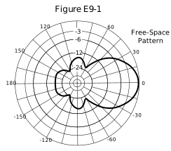
Figure E9-1 - A. 75 degrees
- B. 50 degrees
- C. 25 degrees
- D. 30 degrees
Show answer
B. 50 degrees
Beamwidth is the angle between the two points on the main lobe where the response is 3 dB below the peak. In Figure E9-1 the main lobe, centered on 0 degrees, crosses the -3 dB circle at about 25 degrees on each side, so the beamwidth is about 50 degrees.
- A. At 37.5 degrees either side of the peak the lobe is well below -3 dB, so 75 degrees is wider than the half-power beamwidth.
- C. 25 degrees is the angle from the center of the lobe to one -3 dB point, only half the beamwidth.
- D. 30 degrees is narrower than the angle between the two -3 dB points, which is about 50 degrees.
E9B02
What is the front-to-back ratio of the antenna radiation pattern shown in Figure E9-1?
Figure E9-1 - A. 36 dB
- B. 14 dB
- C. 24 dB
- D. 18 dB
Show answer
D. 18 dB
Front-to-back ratio compares the response in the main direction (0 degrees) with the response in the opposite direction (180 degrees). In Figure E9-1 the rear lobe at 180 degrees reaches about -18 dB, so the front-to-back ratio is 18 dB.
- A. 36 dB is twice the actual value; the rear lobe reaches about -18 dB, not -36 dB.
- B. 14 dB is the front-to-side ratio, read at 90 degrees, not toward the rear.
- C. 24 dB is the value of one of the labeled circles; the rear lobe extends beyond it to about -18 dB.
E9B03
What is the front-to-side ratio of the antenna radiation pattern shown in Figure E9-1?
Figure E9-1 - A. 12 dB
- B. 24 dB
- C. 18 dB
- D. 14 dB
Show answer
D. 14 dB
Front-to-side ratio compares the response in the main direction with the response at right angles to it (90 and 270 degrees). In Figure E9-1 the pattern at 90 degrees is about 14 dB below the main lobe, so the front-to-side ratio is 14 dB.
- A. 12 dB is the value of a labeled circle; the side response is about 14 dB down.
- B. 24 dB is the value of a labeled circle; the side lobes extend well beyond it, to about -14 dB.
- C. 18 dB is the front-to-back ratio, read at 180 degrees, not at the side.
E9B04
What is the front-to-back ratio of the radiation pattern shown in Figure E9-2?
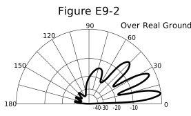
Figure E9-2 - A. 15 dB
- B. 28 dB
- C. 3 dB
- D. 38 dB
Show answer
B. 28 dB
In the elevation pattern of Figure E9-2, the forward direction is toward 0 degrees and the rear is toward 180 degrees. The main lobe reaches 0 dB, while the small lobes toward the rear peak about 28 dB lower, so the front-to-back ratio is 28 dB.
- A. 15 dB is far less than the difference between the main lobe and the small rear lobes in the figure.
- C. 3 dB is the half-power point used for beamwidth, not the front-to-back ratio.
- D. 38 dB is more than the difference between the main lobe and the strongest rear lobe, which is about 28 dB.
E9B05
What type of antenna pattern is shown in Figure E9-2?
Figure E9-2 - A. Elevation
- B. Azimuth
- C. Near field
- D. Polarization
Show answer
A. Elevation
Figure E9-2 is a half circle with 0 degrees and 180 degrees at the horizon and 90 degrees straight up, plotted over real ground. That is an elevation pattern, showing how radiation varies with vertical angle above the horizon.
- B. An azimuth pattern is a full 360-degree circle viewed from above, like Figure E9-1, not a half circle from horizon to horizon.
- C. The near field is the region close to the antenna; radiation patterns such as this one describe the far field.
- D. Polarization describes the orientation of the electric field, not a pattern plotted against elevation angle.
E9B06
What is the elevation angle of peak response in the antenna radiation pattern shown in Figure E9-2?
Figure E9-2 - A. 45 degrees
- B. 75 degrees
- C. 7.5 degrees
- D. 25 degrees
Show answer
C. 7.5 degrees
The elevation angle of peak response is the angle at which the strongest lobe reaches its maximum. In Figure E9-2 the strongest lobe sits close to the horizon, peaking at about 7.5 degrees.
- A. Near 45 degrees there is a higher-angle lobe, but it is weaker than the main lobe.
- B. Near 75 degrees the response is well below the main lobe.
- D. Near 25 degrees there is a second lobe, but it is slightly weaker than the lowest lobe at about 7.5 degrees.
E9B07
What is the difference in radiated power between a lossless antenna with gain and an isotropic radiator driven by the same power?
- A. The power radiated from the directional antenna is increased by the gain of the antenna
- B. The power radiated from the directional antenna is stronger by its front-to-back ratio
- C. They are the same
- D. The power radiated from the isotropic radiator is 2.15 dB greater than that from the directional antenna
Show answer
C. They are the same
Antenna gain does not create power; it redistributes it, concentrating radiation in some directions at the expense of others. A lossless directional antenna and an isotropic radiator fed with the same power radiate the same total power.
- A. Gain increases the signal in the favored direction, not the total radiated power.
- B. Front-to-back ratio describes the shape of the pattern, not the total power radiated.
- D. 2.15 dB is the gain of a half-wave dipole over isotropic in its favored direction, not a difference in total radiated power.
E9B08
What is the far field of an antenna?
- A. The region of the ionosphere where radiated power is not refracted
- B. The region where radiated power dissipates over a specified time period
- C. The region where radiated field strengths are constant
- D. The region where the shape of the radiation pattern no longer varies with distance
Show answer
D. The region where the shape of the radiation pattern no longer varies with distance
Close to an antenna (the near field), the fields are complex and the pattern changes with distance. Farther out, in the far field, the shape of the radiation pattern stays the same at any distance, and field strength falls in inverse proportion to distance.
- A. The far field is a region around the antenna, not a region of the ionosphere.
- B. The far field is not defined by power dissipating over a period of time.
- C. Field strength in the far field keeps decreasing with distance; it is the pattern shape that stays constant.
E9B09
What type of analysis is commonly used for modeling antennas?
- A. Graphical analysis
- B. Method of Moments
- C. Mutual impedance analysis
- D. Calculus differentiation with respect to physical properties
Show answer
B. Method of Moments
Most antenna modeling programs, such as those based on NEC (Numerical Electromagnetics Code), use the Method of Moments. It calculates the current on each part of the antenna and from those currents computes the pattern, gain and feed point impedance.
- A. Graphical analysis is not the method antenna modeling programs use.
- C. Mutual impedance calculations can describe interactions between elements, but the common modeling method is the Method of Moments.
- D. Calculus differentiation with respect to physical properties is not a recognized antenna modeling method.
E9B10
What is the principle of a Method of Moments analysis?
- A. A wire is modeled as a series of segments, each having a uniform value of current
- B. A wire is modeled as a single sine-wave current generator
- C. A wire is modeled as a single sine-wave voltage source
- D. A wire is modeled as a series of segments, each having a distinct value of voltage across it
Show answer
A. A wire is modeled as a series of segments, each having a uniform value of current
Method of Moments analysis divides each wire into short segments and treats the current along each segment as uniform. Solving for those currents, including how every segment affects every other, gives the antenna's impedance and radiation pattern.
- B. The wire is not modeled as one sine-wave current generator; it is divided into many segments.
- C. The wire is not modeled as one voltage source; a source is placed at the feed point and the segment currents are calculated.
- D. The method assigns each segment a uniform current, not a distinct voltage across it.
E9B11
What is a disadvantage of decreasing the number of wire segments in an antenna model below 10 segments per half-wavelength?
- A. Ground conductivity will not be accurately modeled
- B. The resulting design will favor radiation of harmonic energy
- C. The computed feed point impedance may be incorrect
- D. The antenna will become mechanically unstable
Show answer
C. The computed feed point impedance may be incorrect
Method of Moments accuracy depends on having enough segments to represent how current varies along the wire. A common guideline is at least 10 segments per half-wavelength; with fewer, the computed currents, and so the feed point impedance, may be wrong.
- A. Ground conductivity is a separate model setting, not something the number of wire segments controls.
- B. The segment count affects calculation accuracy; it does not make the design favor harmonic radiation.
- D. Segments exist only in the computer model, so their number has nothing to do with mechanical stability.
E9C Practical wire antennas; folded dipoles; phased arrays; effects of ground near antennas
E9C01
What type of radiation pattern is created by two 1/4-wavelength vertical antennas spaced 1/2-wavelength apart and fed 180 degrees out of phase?
- A. Cardioid
- B. Omni-directional
- C. A figure-eight broadside to the axis of the array
- D. A figure-eight oriented along the axis of the array
Show answer
D. A figure-eight oriented along the axis of the array
Two verticals a half wavelength apart and fed 180 degrees out of phase cancel broadside to the array but add along its axis: a wave traveling from one to the other is delayed 180 degrees, which offsets the 180-degree feed difference. The result is a figure-eight pattern pointing along the line through the two antennas (end-fire).
- A. A cardioid comes from quarter-wavelength spacing with a 90-degree phase difference.
- B. Two elements with a 180-degree phase difference produce nulls broadside, so the pattern is not omnidirectional.
- C. A broadside figure-eight comes from feeding the half-wave-spaced pair in phase.
E9C02
What type of radiation pattern is created by two 1/4-wavelength vertical antennas spaced 1/4-wavelength apart and fed 90 degrees out of phase?
- A. Cardioid
- B. A figure-eight end-fire along the axis of the array
- C. A figure-eight broadside to the axis of the array
- D. Omni-directional
Show answer
A. Cardioid
With quarter-wavelength spacing and a 90-degree phase difference, the signals add in the direction of the element whose current lags and cancel in the opposite direction, where the 90-degree spacing delay and 90-degree feed difference combine to 180 degrees. The result is a heart-shaped (cardioid) pattern with one null.
- B. An end-fire figure-eight comes from half-wavelength spacing fed 180 degrees out of phase.
- C. A broadside figure-eight comes from half-wavelength spacing fed in phase.
- D. The 90-degree phasing makes the pattern strongly directional, not omnidirectional.
E9C03
What type of radiation pattern is created by two 1/4-wavelength vertical antennas spaced 1/2-wavelength apart and fed in phase?
- A. Omni-directional
- B. Cardioid
- C. A figure-eight broadside to the axis of the array
- D. A figure-eight end-fire along the axis of the array
Show answer
C. A figure-eight broadside to the axis of the array
Two verticals fed in phase add perpendicular to the line joining them, where their signals arrive together. Along the line, the half-wavelength spacing adds 180 degrees of delay and the signals cancel. The result is a figure-eight broadside to the array.
- A. The cancellation along the array's axis makes the pattern a figure-eight, not omnidirectional.
- B. A cardioid comes from quarter-wavelength spacing with a 90-degree phase difference.
- D. An end-fire figure-eight comes from feeding the pair 180 degrees out of phase.
E9C04
What happens to the radiation pattern of an unterminated long wire antenna as the wire length is increased?
- A. Fewer lobes form with the major lobes increasing closer to broadside to the wire
- B. Additional lobes form with major lobes increasingly aligned with the axis of the antenna
- C. The elevation angle increases, and the front-to-rear ratio decreases
- D. The elevation angle increases, while the front-to-rear ratio is unaffected
Show answer
B. Additional lobes form with major lobes increasingly aligned with the axis of the antenna
As an unterminated long wire is made longer (in wavelengths), its pattern breaks up into more lobes, and the main lobes move closer to the direction of the wire itself. A wire several wavelengths long has its strongest lobes at fairly small angles to the wire.
- A. Making the wire longer adds lobes rather than reducing them, and the main lobes move toward the wire's axis, not broadside.
- C. Lengthening the wire mainly adds lobes and swings them toward the wire's axis; it does not raise the elevation angle.
- D. The main effect of added length is more lobes aligned closer to the wire, not a higher elevation angle.
E9C05
What is the purpose of feeding an off-center-fed dipole (OCFD) between the center and one end instead of at the midpoint?
- A. To create a similar feed point impedance on multiple bands
- B. To suppress off-center lobes at higher frequencies
- C. To resonate the antenna across a wider range of frequencies
- D. To reduce common-mode current coupling on the feed line shield
Show answer
A. To create a similar feed point impedance on multiple bands
Feeding a dipole about one third of the way from one end, rather than at the center, places the feed point where the impedance is roughly similar (a few hundred ohms) on several harmonically related bands. A single balun, often 4:1, can then match it to coax on all those bands.
- B. Off-center feeding is chosen for a similar feed point impedance across bands, not to suppress lobes at higher frequencies.
- C. The wire's length still sets its resonant frequencies; moving the feed point does not make it resonant over a wider range.
- D. Off-center feeding is unbalanced and tends to increase common-mode current on the feed line, so chokes are often added.
E9C06
What is the effect of adding a terminating resistor to a rhombic or long-wire antenna?
- A. It reflects the standing waves on the antenna elements back to the transmitter
- B. It changes the radiation pattern from bidirectional to unidirectional
- C. It changes the radiation pattern from horizontal to vertical polarization
- D. It decreases the ground loss
Show answer
B. It changes the radiation pattern from bidirectional to unidirectional
On an unterminated rhombic or long wire, current reflects from the far end and radiates in both directions. A terminating resistor of about the right value at the far end absorbs the wave instead of reflecting it, so the antenna radiates and receives mainly toward the terminated end: the pattern becomes unidirectional.
- A. The resistor absorbs the wave that reaches the far end; it prevents reflection rather than sending power back toward the transmitter.
- C. Termination changes the pattern's direction, not the antenna's polarization.
- D. The terminating resistor is not used to reduce ground loss; it dissipates power that would otherwise reflect.
E9C07
What is the approximate feed point impedance at the center of a two-wire half-wave folded dipole antenna?
- A. 300 ohms
- B. 72 ohms
- C. 50 ohms
- D. 450 ohms
Show answer
A. 300 ohms
A two-wire folded dipole made from equal-diameter conductors steps up the feed impedance by a factor of 4. With an ordinary half-wave dipole at about 73 ohms, the folded dipole's feed point is about 4 x 73 = 292, or roughly 300 ohms, a good match for 300-ohm twin-lead.
- B. About 72 ohms is the feed point impedance of an ordinary half-wave dipole in free space, not a folded one.
- C. 50 ohms is a common coax impedance, not the feed point impedance of a folded dipole.
- D. 450 ohms is a common impedance of window (ladder) line, not the typical feed impedance of a two-wire folded dipole.
E9C08
What is a folded dipole antenna?
- A. A dipole one-quarter wavelength long
- B. A center-fed dipole with the ends folded down 90 degrees at the midpoint of each side
- C. A half-wave dipole with an additional parallel wire connecting its two ends
- D. A dipole configured to provide forward gain
Show answer
C. A half-wave dipole with an additional parallel wire connecting its two ends
A folded dipole is a half-wave dipole with a second conductor running parallel to it and joined to it at both ends, forming a long, narrow loop. The feed point is at the center of one conductor, which raises the feed impedance to about 300 ohms and widens the bandwidth.
- A. A folded dipole is a half wavelength long, not a quarter wavelength.
- B. Bending the ends of a dipole downward produces a drooping or bent dipole, not a folded dipole.
- D. A folded dipole has essentially the same pattern and gain as an ordinary dipole; it is not designed for forward gain.
E9C09
Which of the following describes a G5RV antenna?
- A. A wire antenna center-fed through a specific length of open-wire line connected to a balun and coaxial feed line
- B. A multi-band trap antenna
- C. A phased array antenna consisting of multiple loops
- D. A wide band dipole using shorted coaxial cable for the radiating elements and fed with a 4:1 balun
Show answer
A. A wire antenna center-fed through a specific length of open-wire line connected to a balun and coaxial feed line
A G5RV is a center-fed wire antenna (about 102 feet in its full-size version) fed through a specific length of open-wire or ladder line, which acts as a matching section. That line connects to a balun or directly to coax that runs to the station.
- B. A G5RV uses no traps; multiband operation comes from the antenna and matching-section lengths, usually with a tuner.
- C. A G5RV is a single wire dipole, not a phased array of loops.
- D. Using shorted coax as the radiating elements describes a coaxial dipole design such as a double bazooka, not a G5RV.
E9C10
Which of the following describes a Zepp antenna?
- A. A horizontal array capable of quickly changing the direction of maximum radiation by changing phasing lines
- B. An end-fed half-wavelength dipole
- C. An omni-directional antenna commonly used for satellite communications
- D. A vertical array capable of quickly changing the direction of maximum radiation by changing phasing lines
Show answer
B. An end-fed half-wavelength dipole
A Zepp antenna is a half-wavelength dipole fed at one end, originally with open-wire line. The name comes from its early use trailing from Zeppelin airships.
- A. Switching phasing lines to steer a horizontal array describes a switchable phased array, not a Zepp.
- C. Omnidirectional satellite antennas include the turnstile and eggbeater, not the Zepp.
- D. Switching phasing lines to steer a vertical array describes a phased vertical array, not a Zepp.
E9C11
How is the far-field elevation pattern of a vertically polarized antenna affected by being mounted over seawater versus soil?
- A. Radiation at low angles decreases
- B. Additional lobes appear at higher elevation angles
- C. Separate elevation lobes will combine into a single lobe
- D. Radiation at low angles increases
Show answer
D. Radiation at low angles increases
Seawater is a much better conductor than soil, so the ground reflection near a vertical antenna loses far less energy and stays in phase to lower angles. The result is stronger radiation at low elevation angles, which favors long-distance contacts.
- A. Seawater increases low-angle radiation from a vertical; it does not decrease it.
- B. Seawater mainly strengthens low-angle radiation from a vertical; it does not add high-angle lobes.
- C. Seawater does not merge separate lobes into one; its effect is to strengthen the low-angle response.
E9C12
Which of the following describes an extended double Zepp antenna?
- A. An end-fed full-wave dipole antenna
- B. A center-fed 1.5-wavelength dipole antenna
- C. A center-fed 1.25-wavelength dipole antenna
- D. An end-fed 2-wavelength dipole antenna
Show answer
C. A center-fed 1.25-wavelength dipole antenna
An extended double Zepp is a center-fed dipole with each half 5/8 wavelength long, for a total of 1.25 wavelengths. That length gives more broadside gain than a half-wave dipole, about 3 dB, before the pattern breaks into more lobes.
- A. An extended double Zepp is center-fed, not end-fed, and it is 1.25 wavelengths long, not 1 wavelength.
- B. An extended double Zepp is 1.25 wavelengths long (two 5/8-wavelength halves), not 1.5 wavelengths.
- D. An extended double Zepp is center-fed and 1.25 wavelengths long, not end-fed and 2 wavelengths long.
E9C13
How does the radiation pattern of a horizontally polarized antenna vary with increasing height above ground?
- A. The takeoff angle of the lowest elevation lobe increases
- B. The takeoff angle of the lowest elevation lobe decreases
- C. The horizontal beamwidth increases
- D. The horizontal beamwidth decreases
Show answer
B. The takeoff angle of the lowest elevation lobe decreases
The pattern of a horizontal antenna over ground is shaped by its reflection from the ground. Raising the antenna (in wavelengths) moves the lowest lobe closer to the horizon, so its takeoff angle decreases; for example, a half-wave-high dipole's lowest lobe peaks at about 30 degrees, and a one-wavelength-high dipole's at about 15 degrees.
- A. Raising the antenna lowers the takeoff angle of the lowest lobe; it does not raise it.
- C. Height above ground mainly changes the elevation pattern, not the horizontal beamwidth.
- D. Height above ground mainly changes the elevation pattern, not the horizontal beamwidth.
E9C14
How does the radiation pattern of a horizontally-polarized antenna mounted above a long slope compare with the same antenna mounted above flat ground?
- A. The main lobe takeoff angle increases in the downhill direction
- B. The main lobe takeoff angle decreases in the downhill direction
- C. The horizontal beamwidth decreases in the downhill direction
- D. The horizontal beamwidth increases in the uphill direction
Show answer
B. The main lobe takeoff angle decreases in the downhill direction
On a slope, the ground falls away in the downhill direction, so the antenna is effectively higher above the reflecting ground that way and the reflection tilts the main lobe downward. The main lobe takeoff angle decreases in the downhill direction (and increases toward the uphill side).
- A. The takeoff angle decreases, not increases, in the downhill direction; it increases toward the uphill side.
- C. Sloping ground mainly changes the elevation angle of the main lobe, not the horizontal beamwidth.
- D. Sloping ground mainly changes the elevation angle of the main lobe, not the horizontal beamwidth.
E9D Yagi antennas; parabolic reflectors; feed point impedance and loading of electrically short antennas; antenna Q; RF grounding
E9D01
How much does the gain of an ideal parabolic reflector antenna increase when the operating frequency is doubled?
- A. 2 dB
- B. 3 dB
- C. 4 dB
- D. 6 dB
Show answer
D. 6 dB
The gain of an ideal parabolic dish is proportional to its area measured in wavelengths, so it rises with the square of frequency. Doubling the frequency increases gain by 2² = 4 times, and 10 x log(4) = 6 dB.
- A. 2 dB is too small; doubling frequency quadruples the gain of an ideal dish, a 6 dB increase.
- B. 3 dB is a doubling of gain, but doubling frequency quadruples the gain of an ideal dish (6 dB).
- C. 4 dB does not follow from the square-law relationship; a factor of 4 is 6 dB.
E9D02
How can two linearly polarized Yagi antennas be used to produce circular polarization?
- A. Stack two Yagis to form an array with the respective elements in parallel planes fed 90 degrees out of phase
- B. Stack two Yagis to form an array with the respective elements in parallel planes fed in phase
- C. Arrange two Yagis on the same axis and perpendicular to each other with the driven elements at the same point on the boom and fed 90 degrees out of phase
- D. Arrange two Yagis collinear to each other with the driven elements fed 180 degrees out of phase
Show answer
C. Arrange two Yagis on the same axis and perpendicular to each other with the driven elements at the same point on the boom and fed 90 degrees out of phase
Circular polarization needs two linear fields at right angles to each other and 90 degrees apart in phase. Mounting two Yagis on the same boom axis with their elements perpendicular (a crossed Yagi), with driven elements at the same point on the boom and fed 90 degrees out of phase, produces it.
- A. Elements in parallel planes have the same polarization, so phasing them 90 degrees does not create the right-angle fields needed for circular polarization.
- B. Stacking two Yagis with parallel elements fed in phase increases gain but keeps the same linear polarization.
- D. Collinear Yagis fed 180 degrees apart have the same linear polarization; that does not create circular polarization.
E9D03
What is the most efficient location for a loading coil on an electrically short whip?
- A. Near the center of the vertical radiator
- B. As low as possible on the vertical radiator
- C. At a voltage maximum
- D. At a voltage null
Show answer
A. Near the center of the vertical radiator
On a short whip, current is nearly constant below a loading coil and tapers toward zero above it. Placing the coil near the center keeps high current along the lower half (raising radiation resistance) without needing the very large, lossy coil that a position near the top would require, so center loading is the efficient compromise.
- B. With the coil at the base, current tapers along the whole whip from base to tip, giving lower radiation resistance and lower efficiency than center loading.
- C. The voltage maximum is at the top of the whip, where a coil would need a very large inductance and would be lossy.
- D. A voltage minimum is not the criterion for coil placement; near the center is the efficient compromise.
E9D04
Why should antenna loading coils have a high ratio of reactance to resistance?
- A. To swamp out harmonics
- B. To lower the radiation angle
- C. To maximize efficiency
- D. To minimize the Q
Show answer
C. To maximize efficiency
A loading coil's resistance wastes power as heat. A coil with a high ratio of reactance to resistance (high Q) provides the needed inductance with little loss, which maximizes the antenna's efficiency.
- A. Coil Q is chosen to reduce loss, not to suppress harmonics.
- B. The coil's reactance-to-resistance ratio does not set the radiation angle.
- D. A high reactance-to-resistance ratio is a high coil Q; the goal is low loss, not low Q.
E9D05
Approximately how long is a Yagi’s driven element?
- A. 234 divided by frequency in MHz
- B. 1005 divided by frequency in MHz
- C. 1/4 wavelength
- D. 1/2 wavelength
Show answer
D. 1/2 wavelength
A Yagi's driven element is a dipole, about one-half wavelength long, fed at its center. The parasitic elements around it are slightly longer (reflector) or shorter (directors).
- A. 234 divided by frequency in MHz gives a quarter wavelength in feet, the length of a vertical or one half of a dipole.
- B. 1005 divided by frequency in MHz gives about a full wavelength in feet, the length of a quad loop, not a Yagi driven element.
- C. A quarter wavelength is the length of a vertical monopole, not a Yagi's dipole driven element.
E9D06
What happens to SWR bandwidth when one or more loading coils are used to resonate an electrically short antenna?
- A. It is increased
- B. It is decreased
- C. It is unchanged if the loading coil is located at the feed point
- D. It is unchanged if the loading coil is located at a voltage maximum point
Show answer
B. It is decreased
An electrically short antenna has low radiation resistance and a large reactance that a loading coil must cancel. The result is a high-Q system whose reactance changes quickly with frequency, so the SWR bandwidth is narrower than that of a full-size antenna.
- A. Loading coils raise the system Q, which narrows rather than increases the SWR bandwidth.
- C. A coil at the feed point still makes a high-Q system, so the bandwidth is narrowed, not unchanged.
- D. Coil location affects efficiency, but loading still narrows the SWR bandwidth.
E9D07
What is an advantage of top loading an electrically short HF vertical antenna?
- A. Lower Q
- B. Greater structural strength
- C. Higher losses
- D. Improved radiation efficiency
Show answer
D. Improved radiation efficiency
A top hat or other capacitive loading at the top of a short vertical keeps the current high farther up the radiator. The more uniform current raises the radiation resistance and reduces the loading inductance needed, so a larger share of the power is radiated rather than lost: radiation efficiency improves.
- A. Lower Q, and so somewhat wider bandwidth, can accompany top loading, but the main advantage is improved radiation efficiency; Q by itself does not measure how much power is radiated.
- B. A top hat adds weight and wind load, so greater structural strength is not an advantage.
- C. Higher losses would be a disadvantage; top loading improves efficiency, so losses take a smaller share of the power.
E9D08
What happens as the Q of an antenna increases?
- A. SWR bandwidth increases
- B. SWR bandwidth decreases
- C. Gain is reduced
- D. More common-mode current is present on the feed line
Show answer
B. SWR bandwidth decreases
An antenna's Q describes how sharply its reactance changes around resonance. A higher-Q antenna's impedance changes faster with frequency, so the range over which SWR stays low (the SWR bandwidth) gets narrower.
- A. Higher Q narrows the SWR bandwidth; it does not widen it.
- C. Q is related to bandwidth, not directly to gain.
- D. Common-mode current on the feed line depends on balance and feed arrangement, not on the antenna's Q.
E9D09
What is the function of a loading coil in an electrically short antenna?
- A. To increase the SWR bandwidth by increasing net reactance
- B. To lower the losses
- C. To lower the Q
- D. To resonate the antenna by cancelling the capacitive reactance
Show answer
D. To resonate the antenna by cancelling the capacitive reactance
An antenna shorter than resonant length has capacitive reactance at its feed point. A loading coil adds inductive reactance that cancels it, bringing the antenna to resonance so it presents a mostly resistive load.
- A. A loading coil cancels reactance (reducing net reactance), and it narrows the SWR bandwidth rather than increasing it.
- B. A loading coil adds its own resistance loss; it does not lower losses.
- C. A loading coil raises the antenna system's Q; it does not lower it.
E9D10
How does radiation resistance of a base-fed whip antenna change below its resonant frequency?
- A. Radiation resistance increases
- B. Radiation resistance decreases
- C. Radiation resistance becomes imaginary
- D. Radiation resistance does not depend on frequency
Show answer
B. Radiation resistance decreases
Below its resonant frequency, a whip is electrically shorter, and radiation resistance falls rapidly as an antenna becomes shorter in wavelengths (roughly with the square of its electrical length). So the radiation resistance decreases, which makes losses a bigger share of the total.
- A. A whip is electrically shorter below resonance, and that lowers its radiation resistance rather than raising it.
- C. Resistance is the real part of impedance; the imaginary part is reactance, so radiation resistance cannot become imaginary.
- D. Radiation resistance depends on electrical length, which changes with frequency.
E9D11
Why do most two-element Yagis with normal spacing have a reflector instead of a director?
- A. Lower SWR
- B. Higher receiving directivity factor
- C. Greater front-to-side
- D. Higher gain
Show answer
D. Higher gain
With typical element spacing, a two-element Yagi using a driven element and reflector gives somewhat more forward gain than one using a driven element and director. That gain advantage is why most two-element Yagis use a reflector.
- A. The choice of reflector over director is made for gain, not to lower SWR, which a matching network handles.
- B. Receiving directivity factor is a receiving-antenna measure, not the reason two-element Yagis use reflectors.
- C. Front-to-side ratio is not the reason; the reflector version is chosen for its higher gain.
E9D12
What is the purpose of making a Yagi’s parasitic elements either longer or shorter than resonance?
- A. Wind torque cancellation
- B. Mechanical balance
- C. Control of phase shift
- D. Minimize losses
Show answer
C. Control of phase shift
A parasitic element is not fed directly; it is excited by the driven element's field. Making it longer than resonance (inductive, a reflector) or shorter (capacitive, a director) controls the phase of its induced current, which sets whether its radiation adds forward or backward.
- A. Element lengths are set for electrical phase, not for wind torque.
- B. Element lengths are set for electrical phase, not for mechanical balance.
- D. Detuning the elements controls the phase of their currents; it is not done to minimize losses.
E9E Impedance matching: matching antennas to feed lines; phasing lines; power dividers
E9E01
Which matching system for Yagi antennas requires the driven element to be insulated from the boom?
- A. Gamma
- B. Beta or hairpin
- C. Shunt-fed
- D. T-match
Show answer
B. Beta or hairpin
A beta or hairpin match connects to both halves of a split driven element at its center, as a balanced feed, so the element must be insulated from the boom. Gamma and T matches connect to points out along a continuous element, whose center can be attached directly to the boom.
- A. A gamma match feeds a continuous element whose center can be attached to the boom.
- C. Shunt feeding taps onto a continuous, grounded element, so it does not require insulating it from the boom.
- D. A T-match is a balanced version of the gamma match and also works with a continuous element attached to the boom at its center.
E9E02
What antenna matching system matches coaxial cable to an antenna by connecting the shield to the center of the antenna and the conductor a fraction of a wavelength to one side?
- A. Gamma match
- B. Delta match
- C. T-match
- D. Stub match
Show answer
A. Gamma match
In a gamma match, the coax shield connects to the electrical center of the driven element, and the center conductor connects through a series capacitor to a rod that taps the element a short distance to one side. Moving the tap point adjusts the impedance transformation.
- B. A delta match fans out from a balanced feed line to two points equally spaced on either side of the center.
- C. A T-match taps both sides of the center symmetrically; it is a balanced version of the gamma.
- D. A stub match uses a short section of transmission line in parallel with the feed line, not a tap on one side of the element.
E9E03
What matching system uses a short length of transmission line connected in parallel with the feed line at or near the feed point?
- A. Gamma match
- B. Delta match
- C. T-match
- D. Stub match
Show answer
D. Stub match
A stub match connects a short section of transmission line, open or shorted at its far end, in parallel with the feed line at or near the feed point. The stub's reactance, set by its length and position, cancels the load's reactance so the line sees a match.
- A. A gamma match taps the driven element with a rod and series capacitor; it is not a stub in parallel with the feed line.
- B. A delta match fans the feed line out to two points on the element; it is not a stub in parallel with the feed line.
- C. A T-match taps both sides of the element with rods; it is not a stub in parallel with the feed line.
E9E04
What is the purpose of the series capacitor in a gamma match?
- A. To provide DC isolation between the feed line and the antenna
- B. To cancel unwanted inductive reactance
- C. To provide a rejection notch that prevents the radiation of harmonics
- D. To transform the antenna impedance to a higher value
Show answer
B. To cancel unwanted inductive reactance
The gamma rod and the element section it parallels form an inductive loop, adding inductive reactance at the feed. The series capacitor cancels that reactance, leaving a resistive match to the coax.
- A. DC isolation is not the purpose; the capacitor is there to cancel the gamma rod's inductive reactance.
- C. The capacitor is in series to cancel reactance at the operating frequency, not to form a harmonic rejection notch.
- D. The impedance transformation comes from the tap point along the element; the capacitor cancels reactance.
E9E05
What Yagi driven element feed point impedance is required to use a beta or hairpin matching system?
- A. Capacitive (driven element electrically shorter than 1/2 wavelength)
- B. Inductive (driven element electrically longer than 1/2 wavelength)
- C. Purely resistive
- D. Purely reactive
Show answer
A. Capacitive (driven element electrically shorter than 1/2 wavelength)
A hairpin is a shunt inductor across the feed point. It works with a driven element that is slightly shorter than a half wavelength, so its feed point is capacitive: the capacitive reactance and the hairpin's inductance form an L network that transforms the element's low resistance up to the feed line's impedance.
- B. An inductive driven element would need a capacitive shunt; the hairpin adds inductance and requires a capacitive element.
- C. A purely resistive element has no capacitive reactance for the hairpin's inductance to work against.
- D. A purely reactive load would accept no power; the hairpin needs a feed point with resistance plus capacitive reactance (an element shorter than resonant).
E9E06
Which of these transmission line impedances would be suitable for constructing a quarter-wave Q-section for matching a 100-ohm feed point impedance to a 50-ohm transmission line?
- A. 50 ohms
- B. 62 ohms
- C. 75 ohms
- D. 90 ohms
Show answer
C. 75 ohms
A quarter-wave matching section needs a characteristic impedance equal to the geometric mean of the two impedances: Z0 = √(50 x 100) = 70.7 ohms. 75-ohm line is closest; it transforms the 100-ohm load to 75² / 100 = 56.25 ohms, an SWR of about 1.13 on the 50-ohm line.
- A. A 50-ohm quarter-wave section transforms 100 ohms to 50² / 100 = 25 ohms, an SWR of 2 on the 50-ohm line.
- B. A 62-ohm section transforms 100 ohms to about 38 ohms, a worse match than 75 ohms gives.
- D. A 90-ohm section transforms 100 ohms to 81 ohms, a worse match than 75 ohms gives.
E9E07
What parameter describes the interaction of a load and transmission line?
- A. Characteristic impedance
- B. Reflection coefficient
- C. Velocity factor
- D. Dielectric constant
Show answer
B. Reflection coefficient
The reflection coefficient describes how a load and a transmission line interact: Γ = (ZL - Z0) / (ZL + Z0), the ratio of reflected to forward voltage at the load. It is 0 for a matched load and has a magnitude of 1 for an open or short.
- A. Characteristic impedance is a property of the line alone, set by its construction, not of the line and load together.
- C. Velocity factor is a property of the line's construction, not of its interaction with the load.
- D. Dielectric constant is a property of the insulating material, not of how a load interacts with the line.
E9E08
What is a use for a Wilkinson divider?
- A. To divide the operating frequency of a transmitter signal so it can be used on a lower frequency band
- B. To feed high-impedance antennas from a low-impedance source
- C. To divide power equally between two 50-ohm loads while maintaining 50-ohm input impedance
- D. To divide the frequency of the input to a counter to increase its frequency range
Show answer
C. To divide power equally between two 50-ohm loads while maintaining 50-ohm input impedance
A Wilkinson divider splits power equally between two outputs, each terminated in 50 ohms, while presenting a 50-ohm input impedance. Its quarter-wave sections and a resistor between the outputs also isolate the outputs from each other; it is commonly used to feed two antennas in a phased or stacked array.
- A. A Wilkinson divider divides power, not frequency; it does not move a signal to a lower band.
- B. Feeding a high-impedance antenna from a low-impedance source is a job for a matching network or transformer.
- D. Dividing an input frequency for a counter is the job of a prescaler, not a power divider.
E9E09
Which of the following is used to shunt feed a grounded tower at its base?
- A. Double-bazooka match
- B. Beta or hairpin match
- C. Gamma match
- D. All these choices are correct
Show answer
C. Gamma match
A grounded tower can be used as a vertical antenna by shunt feeding it: a gamma match connects the coax shield to the grounded base and the center conductor, through a series capacitor, to a wire tapping the tower partway up. Adjusting the tap height and capacitor gives a match without insulating the tower from ground.
- A. A double bazooka is a type of coaxial dipole antenna, not a way to shunt feed a tower.
- B. A beta or hairpin match feeds a split, insulated element, so it does not suit a grounded tower.
- D. Only the gamma match is used this way, so not all the choices are correct.
E9E11
What is the purpose of using multiple driven elements connected through phasing lines?
- A. To control the antenna’s radiation pattern
- B. To prevent harmonic radiation from the transmitter
- C. To allow single-band antennas to operate on other bands
- D. To create a low-angle radiation pattern
Show answer
A. To control the antenna’s radiation pattern
Feeding several driven elements through phasing lines sets the relative phase (and amplitude) of the current in each element. The way their fields add and cancel then controls the radiation pattern, for example making a broadside, end-fire or cardioid pattern.
- B. Harmonic radiation is reduced with filters, not with phasing lines between driven elements.
- C. Phasing lines are cut for a particular band; they do not make single-band antennas work on other bands.
- D. Phasing mainly shapes and steers the pattern; a low radiation angle depends mostly on antenna type, height and ground.
E9F Transmission lines: characteristics of open and shorted feed lines; coax versus open wire; velocity factor; electrical length; coaxial cable dielectrics; microstrip
E9F01
What is the velocity factor of a transmission line?
- A. The ratio of its characteristic impedance to its termination impedance
- B. The ratio of its termination impedance to its characteristic impedance
- C. The velocity of a wave in the transmission line multiplied by the velocity of light in a vacuum
- D. The velocity of a wave in the transmission line divided by the velocity of light in a vacuum
Show answer
D. The velocity of a wave in the transmission line divided by the velocity of light in a vacuum
Velocity factor is the speed of a wave in the transmission line divided by the speed of light in a vacuum. For example, a solid-polyethylene coax with a velocity factor of 0.66 carries signals at 66 percent of the speed of light.
- A. The ratio of characteristic impedance to termination impedance relates to mismatch and SWR, not velocity factor.
- B. The ratio of termination impedance to characteristic impedance relates to mismatch and SWR, not velocity factor.
- C. Velocity factor is a ratio of speeds, so it divides by the speed of light; multiplying gives a meaningless quantity.
E9F02
Which of the following has the biggest effect on the velocity factor of a transmission line?
- A. The characteristic impedance
- B. The transmission line length
- C. The insulating dielectric material
- D. The center conductor resistivity
Show answer
C. The insulating dielectric material
Velocity factor depends mainly on the insulating material (dielectric) between the conductors: it is about 1 / √(dielectric constant). Solid polyethylene gives about 0.66, foam about 0.8 or higher, and air close to 1.
- A. Characteristic impedance and velocity factor are separate; two lines with the same impedance can have different velocity factors if their dielectrics differ.
- B. Velocity factor does not depend on how long the line is.
- D. The center conductor's resistivity affects loss, not the speed of the wave.
E9F03
Why is the electrical length of a coaxial cable longer than its physical length?
- A. Skin effect is less pronounced in the coaxial cable
- B. Skin effect is more pronounced in the coaxial cable
- C. Electromagnetic waves move faster in coaxial cable than in air
- D. Electromagnetic waves move more slowly in a coaxial cable than in air
Show answer
D. Electromagnetic waves move more slowly in a coaxial cable than in air
Waves travel more slowly in coax than in air because of the dielectric, so a wavelength in the cable is physically shorter. A given physical length of cable therefore contains more wavelengths, making its electrical length longer than its physical length.
- A. Skin effect affects loss in the conductors, not how fast the wave travels or the electrical length.
- B. Skin effect affects loss in the conductors, not how fast the wave travels or the electrical length.
- C. Waves travel more slowly in coax than in air, not faster.
E9F04
What impedance does a 1/2-wavelength transmission line present to an RF generator when the line is shorted at the far end?
- A. Very high impedance
- B. Very low impedance
- C. The same as the characteristic impedance of the line
- D. The same as the output impedance of the RF generator
Show answer
B. Very low impedance
A half-wavelength line repeats its load impedance at its input. With a short at the far end, the generator sees a short again: a very low impedance.
- A. A very high impedance appears at the input of a shorted quarter-wavelength line, not a half-wavelength one.
- C. A line presents its characteristic impedance at its input, whatever its length, when it is terminated in that impedance; a shorted or open line does not.
- D. The input impedance depends on the line and its termination, not on the generator's output impedance.
E9F05
What is microstrip?
- A. Special shielding material designed for microwave frequencies
- B. Miniature coax used for low power applications
- C. Short lengths of coax mounted on printed circuit boards to minimize time delay between microwave circuits
- D. Precision printed circuit conductors above a ground plane that provide constant impedance interconnects at microwave frequencies
Show answer
D. Precision printed circuit conductors above a ground plane that provide constant impedance interconnects at microwave frequencies
Microstrip is a precisely sized printed circuit conductor running over a ground plane on the other side of the board. Its width and the board's thickness and dielectric set a constant characteristic impedance, making it a transmission line for connecting microwave circuits.
- A. Microstrip is a printed transmission line, not a shielding material.
- B. Microstrip is a printed conductor over a ground plane, not miniature coax.
- C. Microstrip is printed on the board, not made from short lengths of coax.
E9F06
What is the approximate physical length of an air-insulated, parallel conductor transmission line that is electrically 1/2 wavelength long at 14.10 MHz?
- A. 7.0 meters
- B. 8.5 meters
- C. 10.6 meters
- D. 13.3 meters
Show answer
C. 10.6 meters
Wavelength in meters is 300 / f in MHz: 300 / 14.10 = 21.3 m, and half of that is 10.6 m. Air-insulated parallel line has a velocity factor close to 1, so its physical length is about equal to its electrical length: about 10.6 m.
- A. 7.0 m applies a velocity factor of 0.66, typical of solid-polyethylene coax, not air-insulated line.
- B. 8.5 m applies a velocity factor of 0.8, which is too low for air-insulated line.
- D. 13.3 m divides by 0.8 instead of multiplying; a velocity factor below 1 makes the physical length shorter, not longer.
E9F07
How does parallel conductor transmission line compare to coaxial cable with a plastic dielectric?
- A. Lower loss
- B. Higher SWR
- C. Smaller reflection coefficient
- D. Lower velocity factor
Show answer
A. Lower loss
Parallel-conductor (open-wire or ladder) line is mostly air between the conductors, so it has much less dielectric loss than coax with a plastic dielectric. It typically has lower loss per unit length, especially when SWR on the line is high.
- B. SWR depends on the mismatch between the load and the line's characteristic impedance, not on the type of line.
- C. Reflection coefficient depends on the load and the line's characteristic impedance, not on whether the line is coax or parallel conductor.
- D. Parallel-conductor line has a higher velocity factor than plastic-dielectric coax, not a lower one.
E9F08
Which of the following is a significant difference between foam dielectric coaxial cable and solid dielectric coaxial cable, assuming all other parameters are the same?
- A. Foam dielectric coaxial cable has lower safe maximum operating voltage
- B. Foam dielectric coaxial cable has lower loss per unit of length
- C. Foam dielectric coaxial cable has higher velocity factor
- D. All these choices are correct
Show answer
D. All these choices are correct
Foam dielectric is partly gas, so compared with solid dielectric of the same type it has a lower dielectric constant and lower loss. That gives it a higher velocity factor and lower loss per unit length, but the foam withstands less voltage before breaking down, lowering the safe maximum voltage.
- A. True: foam has lower dielectric strength than solid dielectric, so it breaks down at a lower voltage, but this is only one of the differences.
- B. True: foam dielectric has lower dielectric loss, but this is only one of the differences.
- C. True: foam's lower dielectric constant gives it a higher velocity factor, but this is only one of the differences.
E9F09
What impedance does a 1/4-wavelength transmission line present to an RF generator when the line is shorted at the far end?
- A. Very high impedance
- B. Very low impedance
- C. The same as the characteristic impedance of the transmission line
- D. The same as the generator output impedance
Show answer
A. Very high impedance
A quarter-wavelength line inverts its load impedance: a low impedance at one end appears as a high impedance at the other. A short at the far end therefore looks like a very high impedance (ideally an open circuit) to the generator.
- B. A very low impedance appears at the input of a shorted half-wavelength line, not a quarter-wavelength one.
- C. A line presents its characteristic impedance at its input, whatever its length, when it is terminated in that impedance; a shorted or open line does not.
- D. The input impedance depends on the line and its termination, not on the generator's output impedance.
E9F10
What impedance does a 1/8-wavelength transmission line present to an RF generator when the line is shorted at the far end?
- A. A capacitive reactance
- B. The same as the characteristic impedance of the line
- C. An inductive reactance
- D. Zero
Show answer
C. An inductive reactance
A shorted line less than a quarter wavelength long acts as an inductor. At 1/8 wavelength (45 degrees) the input reactance is X = Z0 x tan(45°) = Z0, an inductive reactance with the same number of ohms as the line's characteristic impedance.
- A. A capacitive reactance appears at the input of an open 1/8-wavelength line, not a shorted one.
- B. The reactance has the same number of ohms as Z0, but it is a pure inductive reactance, not the resistive Z0 a matched line presents.
- D. A shorted line shows zero impedance at its input when it is a half wavelength long (or a multiple of that), not at 1/8 wavelength.
E9F11
What impedance does a 1/8-wavelength transmission line present to an RF generator when the line is open at the far end?
- A. The same as the characteristic impedance of the line
- B. An inductive reactance
- C. A capacitive reactance
- D. Infinite
Show answer
C. A capacitive reactance
An open line less than a quarter wavelength long acts as a capacitor. At 1/8 wavelength (45 degrees) the input reactance is X = Z0 / tan(45°) = Z0, a capacitive reactance with the same number of ohms as the line's characteristic impedance.
- A. The reactance has the same number of ohms as Z0, but it is a pure capacitive reactance, not the resistive Z0 a matched line presents.
- B. An inductive reactance appears at the input of a shorted 1/8-wavelength line, not an open one.
- D. An ideally infinite impedance appears at the input of an open line a half wavelength long, not 1/8 wavelength.
E9F12
What impedance does a 1/4-wavelength transmission line present to an RF generator when the line is open at the far end?
- A. The same as the characteristic impedance of the line
- B. The same as the input impedance to the generator
- C. Very high impedance
- D. Very low impedance
Show answer
D. Very low impedance
A quarter-wavelength line inverts its load impedance. An open at the far end therefore appears as a very low impedance (ideally a short) at the generator.
- A. A line presents its characteristic impedance at its input, whatever its length, when it is terminated in that impedance; a shorted or open line does not.
- B. The line's input impedance is set by the line and its termination, not by the generator.
- C. A very high impedance appears at the input of an open half-wavelength line or a shorted quarter-wavelength line.
E9G The Smith chart
E9G01
Which of the following can be calculated using a Smith chart?
- A. Impedance along transmission lines
- B. Radiation resistance
- C. Antenna radiation pattern
- D. Radio propagation
Show answer
A. Impedance along transmission lines
A Smith chart is a graphical calculator for impedances on transmission lines. Plotting a load impedance and moving around the chart by a line's electrical length shows the impedance at any point along the line.
- B. Radiation resistance depends on the antenna's size and shape; it is calculated or modeled, not found with a Smith chart.
- C. Antenna radiation patterns come from modeling or measurement, not from a Smith chart.
- D. Radio propagation is predicted with propagation tools, not with a Smith chart.
E9G02
What type of coordinate system is used in a Smith chart?
- A. Voltage circles and current arcs
- B. Resistance circles and reactance arcs
- C. Voltage chords and current chords
- D. Resistance lines and reactance chords
Show answer
B. Resistance circles and reactance arcs
A Smith chart's coordinates are circles of constant resistance and arcs of constant reactance. Any impedance plots at the point where its resistance circle and reactance arc cross.
- A. A Smith chart plots resistance and reactance, not voltage and current.
- C. A Smith chart has no voltage or current chords; it uses resistance circles and reactance arcs.
- D. Constant-resistance values on a Smith chart are circles, not lines, and reactance values are arcs.
E9G03
Which of the following is often determined using a Smith chart?
- A. Beam headings and radiation patterns
- B. Satellite azimuth and elevation bearings
- C. Impedance and SWR values in transmission lines
- D. Point-to-point propagation reliability as a function of frequency
Show answer
C. Impedance and SWR values in transmission lines
Smith charts are used to find impedance and SWR along transmission lines, for example the impedance at the transmitter end of a line feeding a mismatched antenna, and to design matching networks.
- A. Beam headings come from great-circle maps and radiation patterns from modeling, not from a Smith chart.
- B. Satellite azimuth and elevation come from tracking software or calculations, not from a Smith chart.
- D. Propagation reliability is estimated with propagation prediction programs, not with a Smith chart.
E9G04
What are the two families of circles and arcs that make up a Smith chart?
- A. Inductance and capacitance
- B. Reactance and voltage
- C. Resistance and reactance
- D. Voltage and impedance
Show answer
C. Resistance and reactance
A Smith chart is made of two families: circles of constant resistance and arcs of constant reactance. Inductive reactance is plotted in the upper half and capacitive reactance in the lower half.
- A. Inductance and capacitance appear on the chart as reactance values; the families are resistance and reactance.
- B. Voltage is not one of the families of curves on a Smith chart.
- D. Voltage is not plotted on a Smith chart; impedance is located by its resistance and reactance.
E9G05
Which of the following is a common use for a Smith chart?
- A. Determine the length and position of an impedance matching stub
- B. Determine the impedance of a transmission line, given the physical dimensions
- C. Determine the gain of an antenna given the physical and electrical parameters
- D. Determine the loss/100 feet of a transmission line, given the velocity factor and conductor materials
Show answer
A. Determine the length and position of an impedance matching stub
A common Smith chart task is designing a stub match: the chart shows how far from the load to place a stub and how long the stub must be to cancel the reactance there.
- B. Characteristic impedance from physical dimensions is calculated with a formula, not a Smith chart.
- C. Antenna gain comes from modeling or measurement, not a Smith chart.
- D. Line loss per 100 feet comes from manufacturer data or calculation, not a Smith chart.
E9G06
On the Smith chart shown in Figure E9-3, what is the name for the large outer circle on which the reactance arcs terminate?
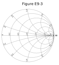
Figure E9-3 - A. Prime axis
- B. Reactance axis
- C. Impedance axis
- D. Polar axis
Show answer
B. Reactance axis
The large outer circle of a Smith chart is where resistance is zero, so every point on it is a pure reactance. It is called the reactance axis, and the reactance arcs end on it.
- A. "Prime axis" is not a Smith chart term; the center point is called the prime center.
- C. The outer circle is not called the impedance axis; it represents pure reactance.
- D. "Polar axis" is not the name of the Smith chart's outer circle.
E9G07
On the Smith chart shown in Figure E9-3, what is the only straight line shown?
Figure E9-3 - A. The reactance axis
- B. The current axis
- C. The voltage axis
- D. The resistance axis
Show answer
D. The resistance axis
The horizontal line through the center of a Smith chart is where reactance is zero, so it holds the pure resistances, from zero on the left to infinity on the right. It is the resistance axis and is the only straight line on the chart.
- A. The reactance axis is the large outer circle, not a straight line.
- B. A Smith chart has no current axis.
- C. A Smith chart has no voltage axis.
E9G08
How is a Smith chart normalized?
- A. Reassign the reactance axis with resistance values
- B. Reassign the resistance axis with reactance values
- C. Reassign the prime center’s impedance value
- D. Reassign the prime center to the reactance axis
Show answer
C. Reassign the prime center’s impedance value
Normalizing assigns the chart's prime center a reference impedance, usually the line's characteristic impedance, and divides every impedance by it. On a 50-ohm system, 50 ohms plots at the center as 1.0 and 100 + j50 ohms plots as 2 + j1.
- A. Normalizing does not swap axes; it scales impedances by the value assigned to the prime center.
- B. Normalizing does not relabel the resistance axis with reactance values.
- D. Normalizing does not move the prime center; it assigns the center an impedance value.
E9G09
What third family of circles is often added to a Smith chart during the process of designing impedance matching networks?
- A. Constant-SWR circles
- B. Transmission line length circles
- C. Coaxial-length circles
- D. Radiation-pattern circles
Show answer
A. Constant-SWR circles
Constant-SWR circles, centered on the prime center, are often added to a Smith chart. Moving along a lossless line keeps SWR constant, so the impedance travels around such a circle; this makes the circles useful when designing matching networks.
- B. Line length is read from the wavelength scales around the outside of the chart, not from added circles.
- C. There are no coaxial-length circles on a Smith chart.
- D. Radiation patterns are not shown on a Smith chart.
E9G10
What do the arcs on a Smith chart represent?
- A. Frequency
- B. SWR
- C. Points with constant resistance
- D. Points with constant reactance
Show answer
D. Points with constant reactance
The arcs on a Smith chart each connect points of equal reactance, inductive above the resistance axis and capacitive below it. The full circles connect points of equal resistance.
- A. Frequency is not plotted directly on a Smith chart.
- B. SWR is shown by constant-SWR circles centered on the prime center, not by the reactance arcs.
- C. Points of constant resistance lie on the full circles, not the arcs.
E9G11
In what units are the wavelength scales on a Smith chart calibrated?
- A. In fractions of transmission line electrical frequency
- B. In fractions of transmission line electrical wavelength
- C. In fractions of antenna electrical wavelength
- D. In fractions of antenna electrical frequency
Show answer
B. In fractions of transmission line electrical wavelength
The scales around the edge of a Smith chart are marked in fractions of a wavelength along the transmission line, measured as electrical length. One full trip around the chart equals a half wavelength of line.
- A. The scales are in fractions of wavelength, not frequency.
- C. The wavelength scales refer to the transmission line, not the antenna.
- D. The scales are in fractions of transmission line wavelength, not antenna frequency.
E9H Receiving antennas: radio direction finding (RDF) techniques; Beverage antennas; single- and multiple-turn loops
E9H01
When constructing a Beverage antenna, which of the following factors should be included in the design to achieve good performance at the desired frequency?
- A. Its overall length must not exceed 1/4 wavelength
- B. It must be mounted more than 1 wavelength above ground
- C. It should be configured as a four-sided loop
- D. It should be at least one wavelength long
Show answer
D. It should be at least one wavelength long
A Beverage is a long, low wire receiving antenna, usually terminated at the far end. It needs to be at least one wavelength long at the operating frequency to develop useful directivity; longer generally gives more directivity.
- A. A Beverage needs to be at least a wavelength long; a quarter wavelength is far too short.
- B. Beverages are mounted low, typically a few feet to about 10 feet above ground, not over a wavelength high.
- C. A Beverage is a long single wire, not a four-sided loop.
E9H02
Which is generally true for 160- and 80-meter receiving antennas?
- A. Atmospheric noise is so high that directivity is much more important than losses
- B. They must be erected at least 1/2 wavelength above the ground to attain good directivity
- C. Low loss coax transmission line is essential for good performance
- D. All these choices are correct
Show answer
A. Atmospheric noise is so high that directivity is much more important than losses
On 160 and 80 meters, atmospheric noise is strong enough to set the reception limit. An inefficient receiving antenna lowers signal and noise together, so what improves reception is directivity that rejects noise and interference from other directions.
- B. Good low-band receiving antennas such as Beverages work close to the ground; half-wavelength height is not required.
- C. Because atmospheric noise is high, some feed line loss reduces signal and noise together and is not critical.
- D. Only the statement about directivity is generally true, so not all the choices are correct.
E9H03
What is receiving directivity factor (RDF)?
- A. Forward gain compared to the gain in the reverse direction
- B. Relative directivity compared to isotropic
- C. Relative directivity compared to a dipole
- D. Peak antenna gain compared to average gain over the hemisphere around and above the antenna
Show answer
D. Peak antenna gain compared to average gain over the hemisphere around and above the antenna
Receiving directivity factor (RDF) compares an antenna's gain in its peak direction with its average gain over the whole hemisphere around and above it. A high RDF means the antenna favors the wanted direction over noise arriving from all others.
- A. Forward gain compared with reverse gain is the front-to-back ratio.
- B. Directivity compared with isotropic describes gain in dBi, not RDF.
- C. Directivity compared with a dipole describes gain in dBd, not RDF.
E9H04
What is the purpose of placing an electrostatic shield around a small-loop direction-finding antenna?
- A. It adds capacitive loading, increasing the bandwidth of the antenna
- B. It eliminates unbalanced capacitive coupling to the antenna’s surroundings, improving the depth of its nulls
- C. It eliminates tracking errors caused by strong out-of-band signals
- D. It increases signal strength by providing a better match to the feed line
Show answer
B. It eliminates unbalanced capacitive coupling to the antenna’s surroundings, improving the depth of its nulls
A small loop can pick up signals through stray capacitive coupling to nearby objects and to the feed line, acting like a small unbalanced vertical. An electrostatic shield removes this unwanted coupling so the loop responds only as a balanced loop, which makes its nulls deeper and its bearings sharper.
- A. The shield is used to remove unbalanced coupling, not to add loading or increase bandwidth.
- C. The shield does not address strong out-of-band signals; that is a receiver selectivity problem.
- D. The shield does not improve the match to the feed line; its purpose is to deepen the nulls.
E9H05
What challenge is presented by a small wire-loop antenna for direction finding?
- A. It has a bidirectional null pattern
- B. It does not have a clearly defined null
- C. It is practical for use only on VHF and higher bands
- D. All these choices are correct
Show answer
A. It has a bidirectional null pattern
A small loop has two equally deep nulls, 180 degrees apart, along the loop's axis. A null tells you the line the signal comes from but not which of the two opposite directions, so a second bearing or a sense antenna is needed to resolve the ambiguity.
- B. A small loop's nulls are sharp and well defined; that is what makes it useful for direction finding.
- C. Small loops are widely used for direction finding on MF and HF, not only on VHF and higher.
- D. Only the bidirectional null is a challenge, so not all the choices are correct.
E9H06
What indicates the correct value of terminating resistance for a Beverage antenna?
- A. Maximum feed point DC resistance at the center of the desired frequency range
- B. Minimum low-angle front-to-back ratio at the design frequency
- C. Maximum DC current in the terminating resistor
- D. Minimum variation in SWR over the desired frequency range
Show answer
D. Minimum variation in SWR over the desired frequency range
When a Beverage is terminated in a resistance close to its characteristic impedance, little energy reflects from the far end, and the feed point impedance stays nearly constant with frequency. So the correct termination shows as the least variation in SWR across the frequency range.
- A. Feed point DC resistance does not indicate the correct RF termination.
- B. The goal of termination is maximum front-to-back ratio, not minimum.
- C. Correct termination is judged by a steady SWR across the band, not by the current in the terminating resistor.
E9H07
What is the function of a Beverage antenna’s termination resistor?
- A. Increase the front-to-side ratio
- B. Absorb signals from the reverse direction
- C. Decrease SWR bandwidth
- D. Eliminate harmonic reception
Show answer
B. Absorb signals from the reverse direction
Signals arriving from the terminated end travel toward that end of the wire and are absorbed in the termination resistor instead of reflecting back to the receiver. Signals from the other direction travel toward the receiver end, so the antenna becomes unidirectional.
- A. The resistor's purpose is to reject signals from the rear, not to increase front-to-side ratio.
- C. Termination makes the SWR steady across frequency, broadening rather than decreasing the SWR bandwidth.
- D. The termination resistor does not affect harmonic reception.
E9H08
What is the function of a sense antenna?
- A. It modifies the pattern of a DF antenna to provide a null in only one direction
- B. It increases the sensitivity of a DF antenna array
- C. It allows DF antennas to receive signals at different vertical angles
- D. It provides diversity reception that cancels multipath signals
Show answer
A. It modifies the pattern of a DF antenna to provide a null in only one direction
A loop's figure-eight pattern has two nulls, which leaves a 180-degree ambiguity. A sense antenna, usually a small vertical, is combined with the loop in the right phase and amplitude to turn the pattern into a cardioid with a single null, showing which direction the signal comes from.
- B. The sense antenna's job is to resolve direction ambiguity, not to increase sensitivity.
- C. A sense antenna does not let the array receive at different vertical angles.
- D. A sense antenna is not a diversity antenna for canceling multipath.
E9H09
What type of radiation pattern is created by a single-turn, terminated loop such as a pennant antenna?
- A. Cardioid
- B. Bidirectional
- C. Omnidirectional
- D. Hyperbolic
Show answer
A. Cardioid
A pennant (or flag) is a single-turn loop with a resistor in one side. The terminating resistor makes the loop respond like a combination of a small loop and a short vertical, giving a cardioid pattern with a single null, useful for low-band receiving.
- B. A bidirectional, figure-eight pattern comes from a small loop without a termination.
- C. The terminated loop is directional, not omnidirectional.
- D. "Hyperbolic" is not a type of antenna radiation pattern.
E9H10
How can the output voltage of a multiple-turn receiving loop antenna be increased?
- A. By reducing the permeability of the loop shield
- B. By utilizing high impedance wire for the coupling loop
- C. By increasing the number of turns and/or the area enclosed by the loop
- D. All these choices are correct
Show answer
C. By increasing the number of turns and/or the area enclosed by the loop
A receiving loop's output voltage is proportional to the number of turns and the area each turn encloses. Adding turns, enlarging the loop, or both increases the voltage it delivers.
- A. Reducing a shield's permeability does not increase the loop's output.
- B. Using high-impedance wire for a coupling loop does not raise the loop's output voltage.
- D. Only more turns and larger area increase the output, so not all the choices are correct.
E9H11
What feature of a cardioid pattern antenna makes it useful for direction-finding antennas?
- A. A very sharp peak
- B. A single null
- C. Broadband response
- D. High radiation angle
Show answer
B. A single null
A cardioid pattern has one deep null opposite its broad maximum. Rotating the antenna until the signal fades into that single null gives a bearing without the 180-degree ambiguity of a loop's two nulls.
- A. A cardioid's peak is broad, not sharp; the useful feature is its single null.
- C. Broadband response is not what makes a cardioid useful for direction finding.
- D. A high radiation angle is not a direction-finding advantage of a cardioid.